English



How to Calculate Overhead Crane Duty Cycle
Date: 2026-10-15 Share:
Overhead crane duty cycle calculation turns a production sequence into engineering inputs for selecting the crane, hoist, motors, brakes, gearboxes, wheels, controls, and supporting structure. Rated capacity alone cannot describe how hard a crane will work.
A reliable calculation separates three quantities: elapsed cycle time, total crane motion time, and the running time of each mechanism. It must also record cycle frequency, starts and reversals, idle time, load spectrum, operating environment, and required design life.
What Is a Crane Operating Cycle?
Define one complete cycle
A crane operating cycle is one repeatable material-handling sequence. Its exact boundary depends on the process, but a typical cycle includes:
- Positioning the empty hook or attachment.
- Engaging the load.
- Lifting to a safe travel height.
- Moving the trolley and bridge to the destination.
- Lowering and releasing the load.
- Returning the empty crane for the next pickup.
Use the same start and finish points for every observation so measured cycles remain comparable.
Separate elapsed, motion, and idle time
Elapsed cycle time covers everything from the start of one cycle to the start of the next. It can include powered movement, load attachment, positioning, process waiting, and short delays.
Crane motion time covers the minutes during which one or more mechanisms move. Mechanism running time is narrower: it records the operating time of the hoist, trolley, and bridge separately.
Idle time is the scheduled period when no mechanism runs. Frequent restarts after short pauses may still increase motor and brake heating.
Crane Duty Cycle Calculation Method
Step 1: Measure distances and speeds
List the average vertical hook travel, trolley travel, and bridge travel for both loaded and empty movements. Record normal operating speeds rather than relying automatically on nameplate maximums.
For a constant-speed estimate:
Movement time (min) = Travel distance (m) / Speed (m/min)
This is a planning formula. Actual observations are preferable because acceleration, deceleration, creep speed, and positioning add time.
Step 2: Calculate each mechanism separately
For the hoist:
Hoist time per cycle = Loaded lifting time + Loaded lowering time + Any empty-hook vertical movement
Use the same principle for the trolley and bridge. Include outbound and return movements and do not assume that every movement occurs at full speed.
Step 3: Add handling and waiting time
Add time for attaching, releasing, aligning, and waiting. These minutes affect throughput and elapsed cycle time but are not automatically motor running time.
If hoisting and traveling occur simultaneously, measured elapsed time may be shorter than the sum of all mechanism times. Each mechanism must still be totaled independently for equipment selection.
Step 4: Convert the cycle into daily frequency
Cycles per day = Cycles per hour x Scheduled operating hours per day
Daily running time for one mechanism (hours) = Cycles per day x Mechanism running minutes per cycle / 60
Calculate these values for normal production and anticipated peaks.
Step-by-Step Crane Working Time Calculation
Example operating data
Consider a 10-ton overhead crane serving an eight-hour production shift. The example assumes six cycles per hour and the following average sequence:
- Loaded lift: 6 m at 4 m/min
- Loaded lowering: 6 m at 4 m/min
- Loaded trolley travel: 20 m at 20 m/min
- Empty trolley return: 20 m at 20 m/min
- Loaded bridge travel: 30 m at 30 m/min
- Empty bridge return: 30 m at 30 m/min
- Load attachment, release, and positioning: 1 minute per cycle
The example assumes no additional empty-hook vertical movement. A real study must include every required movement.
Calculate one cycle
The loaded lift takes 6 / 4 = 1.5 minutes. Loaded lowering also takes 1.5 minutes, so hoist running time is 3 minutes per cycle.
Loaded trolley travel takes 20 / 20 = 1 minute. The return takes another minute, giving 2 minutes of trolley running time.
Loaded bridge travel takes 30 / 30 = 1 minute. The return also takes 1 minute, giving 2 minutes of bridge running time.
The sequence therefore contains 7 mechanism-minutes plus 1 minute for handling and positioning. If none of the motions overlap, elapsed cycle time is 8 minutes.
Calculate daily operating time correctly
At six cycles per hour for eight hours:
Cycles per day = 6 x 8 = 48 cycles
Cycle-occupied time = 48 x 8 / 60 = 6.4 hours per day
This 6.4-hour result describes the portion of the shift occupied by complete cycles. It must not be entered as the daily running time of every mechanism.
The mechanism totals are:
- Hoist: 48 x 3 / 60 = 2.4 hours per day
- Trolley: 48 x 2 / 60 = 1.6 hours per day
- Bridge: 48 x 2 / 60 = 1.6 hours per day
Time outside the eight-minute cycles is 1.6 hours per shift. Handling time is not assigned to a motor unless a mechanism is running.
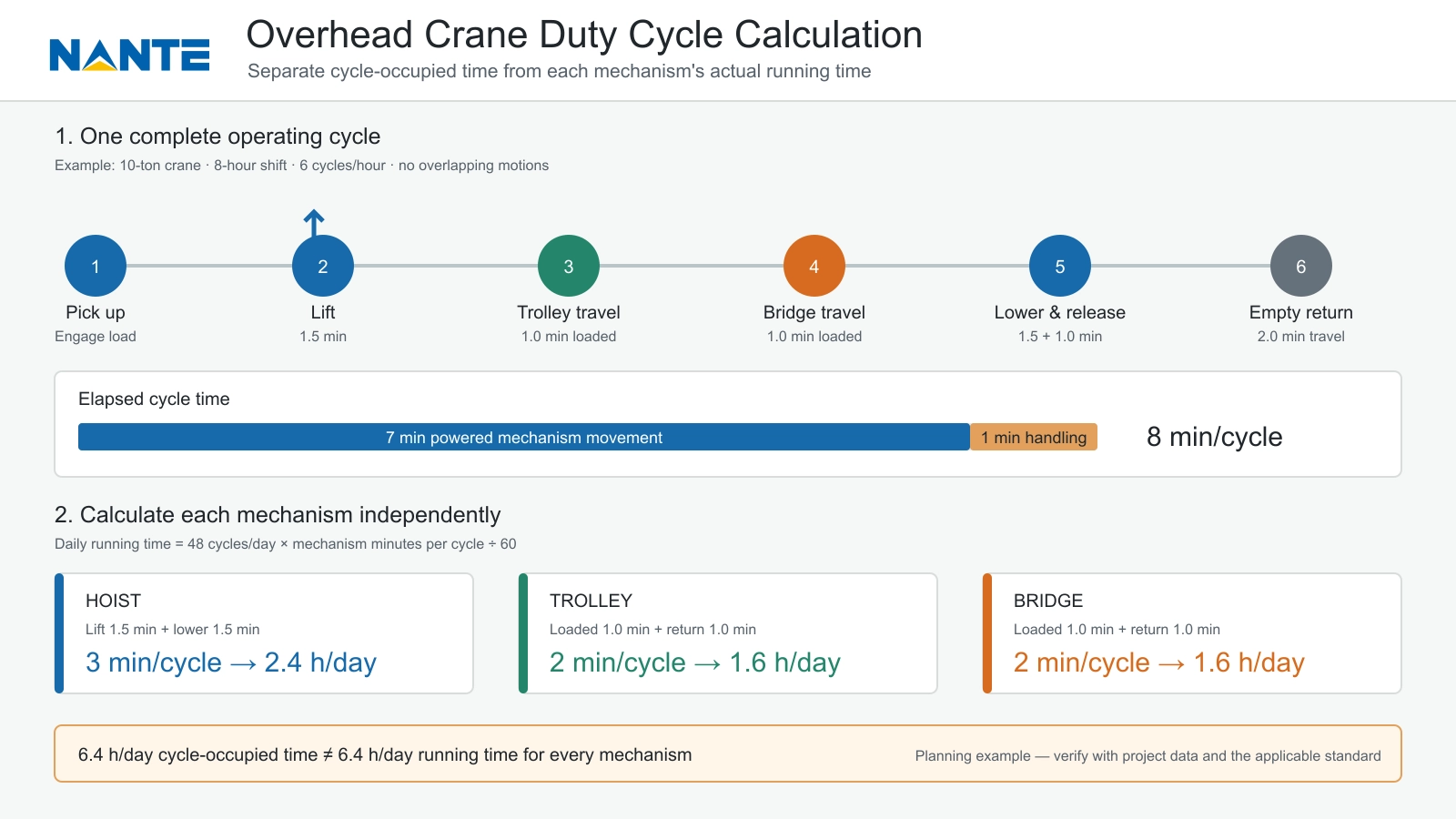
img.Overhead crane operating cycle and daily mechanism running time calculation.webp
Add Load Spectrum to the Calculation
Why average load is not enough
Two cranes can have identical capacity and running time but different fatigue exposure. Repeated lifts near rated capacity impose greater stress than light loads.
Create load bands from production data, such as 0–25%, 26–50%, 51–75%, and 76–100% of rated load. Record the percentage of total cycles in each band, including below-the-hook devices when relevant.
Use a preliminary load-spectrum factor
For early engineering comparison, a cubic load-spectrum factor may be written as:
K = Sum of [p(i) x (Q(i) / Qrated)^3]
Here, p(i) is the fraction of cycles in a load band, Q(i) is its representative lifted load, and Qrated is rated capacity. The cycle fractions must total 1.00.
For 20% of cycles at 25% load, 40% at 50%, 30% at 75%, and 10% at 100%:
K = (0.20 x 0.25^3) + (0.40 x 0.50^3) + (0.30 x 0.75^3) + (0.10 x 1.00^3) = approximately 0.28
This value summarizes the load mix but cannot assign a duty class by itself. The applicable standard, utilization, mechanism scope, and design-life rules must also be applied.
Connect the Results to FEM, ISO, and CMAA
Treat each system within its scope
FEM 9.511 is commonly referenced for hoist mechanism classification using load spectrum and daily operating time. ISO 4301-1 classifies cranes and mechanisms using utilization and load-spectrum parameters. CMAA service classes A through F describe North American crane service conditions from standby or infrequent service through continuous severe service.
These systems should not be converted through a one-line equivalency table. An FEM hoist class is not automatically the class of the complete crane, and a CMAA class is not a renamed ISO mechanism group.
The specification should identify the required standard, edition, equipment scope, and service class. Suppliers should show their assumptions and calculation basis. The crane duty classification guide provides a starting comparison.
How Duty Cycle Changes Component Selection
Hoist, wire rope, and gearbox
Higher cycle frequency and a heavier load spectrum increase fatigue demands on gears, bearings, drums, sheaves, hooks, and rope. Reeving design, rope bending frequency, drum geometry, inspection access, and expected replacement intervals should match the calculated service.
The selected wire rope hoist should therefore be reviewed against capacity, lifting height, speed, running hours, load spectrum, and environmental conditions—not capacity alone.
Crane motors and brakes
Motor selection must account for power, thermal duty, starts per hour, acceleration, reversals, control method, and ambient temperature. The crane motor power calculation supports power review, but power and duty classification remain separate checks.
Brakes must handle stopping frequency, holding torque, lowering conditions, emergency stops, and heat dissipation. A hoist brake problem guide can help maintenance teams recognize drift-related symptoms, but brake sizing requires project-specific engineering.
Structure, travel system, and controls
Crane duty also affects girder fatigue, wheels, rails, end carriages, buffers, contactors, variable-frequency drives, and limit switches. High-cycle service may justify condition monitoring and a critical-spares plan.
When comparing suppliers, the purchasing team should normalize equipment scope, controls, runway interfaces, documents, testing, packing, freight, installation, commissioning, training, warranty, spares, and exclusions before comparing price.
Frequently Asked Questions
What is an overhead crane duty cycle?
An overhead crane duty cycle describes how frequently and intensively the crane operates. It considers operating cycles, mechanism running time, load spectrum, starts and stops, travel movements, idle periods, and expected service life.
Is duty cycle the same as operating time?
No. Operating time measures how long a crane or mechanism runs. Duty cycle also considers load severity, cycle frequency, starts, reversals, and operating conditions. Two cranes with equal running hours can therefore require different duty classifications.
How is crane working time calculated?
Calculate each mechanism separately:
Daily mechanism running time (hours) = Cycles per day x Mechanism running time per cycle (minutes) / 60
Handling and waiting periods belong to elapsed cycle time but should not be counted as motor running time unless the mechanism is operating.
Does rated capacity determine crane duty classification?
No. Rated capacity defines the maximum permitted load. Crane duty classification also depends on how often the crane operates, the distribution of lifted loads, total operating hours, starts per hour, and required design life.
Can FEM, ISO, and CMAA classes be converted directly?
Not reliably. FEM, ISO, and CMAA use different classification scopes and methods. Approximate comparison tables may support early planning, but the final classification must identify the applicable standard, edition, and whether it covers a mechanism or the complete crane.
Should idle time be included in the calculation?
Idle time should be recorded separately from powered running time. Although it does not always count as mechanism operating time, short idle periods followed by frequent starts can affect motor heating, brake wear, contactors, and control components.
Prepare a Duty-Cycle Specification
Information to send with an inquiry
A useful project brief should include:
- Rated capacity, typical loads, and load-band percentages
- Span, lifting height, and travel distances
- Hoisting, trolley, and bridge speeds
- Cycles per hour, shifts per day, and days per year
- Starts, stops, reversals, and simultaneous motions
- Required design life and anticipated production growth
- Temperature, dust, humidity, corrosion, and hazardous-area conditions
- Applicable FEM, ISO, CMAA, or owner specifications
- Power supply, control method, installation scope, and delivery destination
From the second half of the selection process onward, Nante Crane can be evaluated using the same operating profile, compliance matrix, drawings, component data, inspection requirements, and document list supplied to every bidder.
Request an auditable engineering response
The proposal should identify the cycle definition, mechanism running times, load spectrum, selected classifications, component ratings, applicable standards, testing scope, and maintenance assumptions. Any excluded movement or production condition should be stated clearly.
For a project-specific review, purchasing teams can submit capacity, span, lifting height, speeds, load distribution, cycle frequency, daily schedule, environment, destination, and required standards. Nante Crane can use these inputs to review the operating profile and prepare an equipment recommendation or technical proposal through the overhead crane duty-cycle inquiry.