English


How to Calculate Jib Crane Overturning Moment: Calculation Guide
Date: 2026-11-12 Share:
A jib crane overturning moment calculation adds the moments created by forces acting away from a defined support reference. Vertical loads create bending through their horizontal radius; horizontal forces create bending through their application height.
The general relationship is M = r × F. For a simple planar case, this reduces to force multiplied by the perpendicular distance to its line of action.
The calculation helps engineering and purchasing teams verify supplier reactions, compare equipment configurations, and establish foundation inputs. An incomplete load model can understate anchorage demand, trigger civil redesign, or leave important installation work outside the quotation.
Understand Why a Jib Crane Creates Overturning Moment
Follow the Load From Hook to Foundation
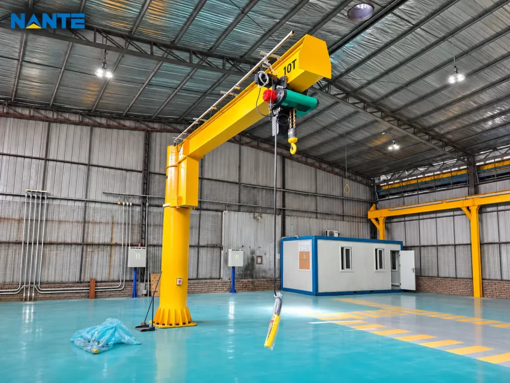
A suspended load acts away from the mast axis. Although its weight acts vertically, that offset creates a bending moment tending to rotate the crane toward the load.
The boom transfers this action into the mast. At the base, bending is resisted through the base plate, compression contact, and anchorage tension, according to the connection design.
The foundation then transfers the combined forces into the supporting ground or structure. Each interface needs compatible reaction data; a crane capacity rating alone does not establish foundation adequacy.
Distinguish Radius From Height
A vertical load’s moment depends on its horizontal distance from the reference point. Raising the same vertical load without changing that distance does not directly increase its first-order gravity moment.
A horizontal force behaves differently. Increasing its application height increases its bending lever arm.
This explains why two cranes with identical capacity and radius can have different base reactions when their heights, equipment weights, or operating systems differ.
Establish the Force Diagram and Calculation Reference
Define the Coordinate System
For a free-standing crane, place reference O at the mast-base interface and define:
- +x:horizontally outward along the illustrated boom.
- +y:horizontally perpendicular to the boom.
- +z:vertically upward.
- Mx and My:bending moments about horizontal axes.
- Tz:torsion about the vertical mast axis.
Positive moments follow the right-hand rule. These axes describe one boom position; foundation checks also require reactions in fixed support axes throughout the permitted rotation.
Identify Each Force and Lever Arm
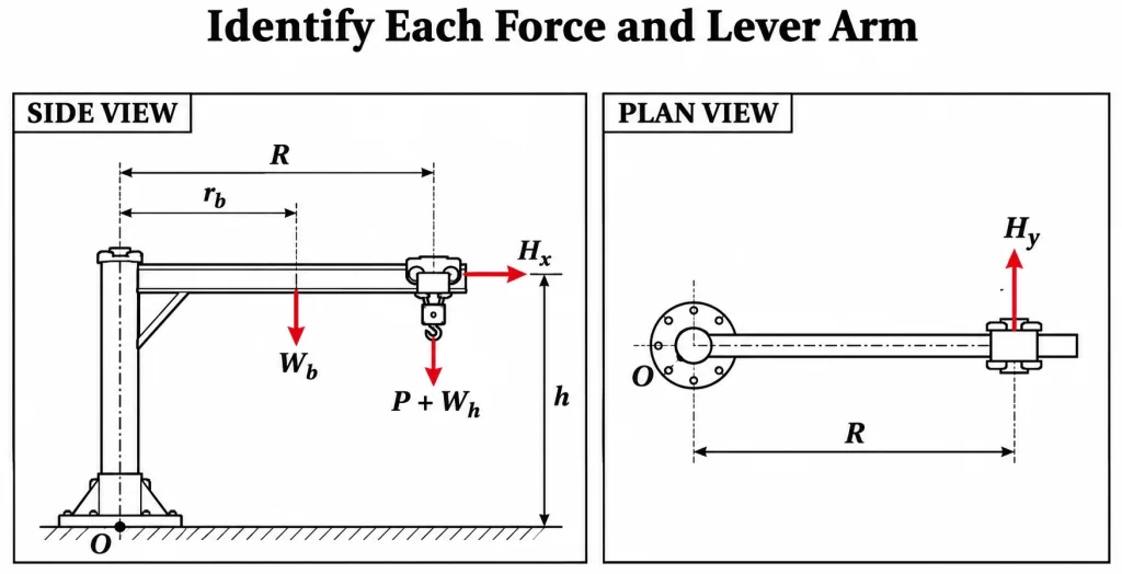
P is suspended load including applicable rigging; Wh is hoist/trolley weight; Wb is boom weight. The boom center of gravity lies at rb.
The schematic places P and Wh at radius R. Actual equipment may require separate center-of-gravity coordinates.
Use the load-line radius from the general arrangement, rather than overall steel length. The jib crane working radius guidance explains the relevant dimensional distinctions.
Calculate Jib Crane Overturning Moment Components
Apply the Force–Moment Equations
For force F = (Fx, Fy, Fz) at position r = (x, y, z), moments about O are:
Mx = yFz − zFy
My = zFx − xFz
Tz = xFy − yFx
Calculate each contribution separately, then add signed components. These equations describe applied load effects; balancing support reactions act in opposite directions.
A downward weight W on the boom centerline has Fz = −W and y = 0, giving My = xW. The horizontal offset is the lever arm because it is perpendicular to gravity.
Separate Bending From Torsion
A radial horizontal force Hx at height h produces:
My = hHx
A tangential force Hy at radius R and height h produces:
Mx = −hHy
Tz = RHy
The tangential force therefore bends the mast and twists it. Torsion must remain separate from overturning bending.
The resultant bending magnitude is:
Mb = √(Mx² + My²)
This summarizes bending magnitude but does not replace signed component reactions needed for anchors and foundations.
Use Compatible Load Cases
Horizontal actions may arise from acceleration, braking, slewing, load motion, or environmental exposure. Their values require supplier data and the project design basis.
Do not combine unrelated maxima into an invented operating condition. Request simultaneous reaction sets, identifying included operating allowances and structural load factors.
Worked Jib Crane Base Moment Example
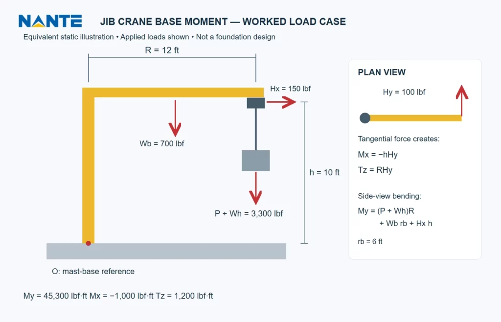
Step 1: Define Equivalent Static Inputs
Assume the following forces act simultaneously in one illustrative equivalent static load case. Horizontal forces are assumed inputs, not predictions for actual equipment.
| Input | Value |
| Suspended load P, including rigging | 3,000 lbf |
| Hoist/trolley weight Wh | 300 lbf |
| Load and hoist/trolley radius R | 12 ft |
| Boom weight Wb | 700 lbf |
| Boom center-of-gravity radius rb | 6 ft |
| Centered mast weight | 900 lbf |
| Radial force Hx | +150 lbf |
| Tangential force Hy | +100 lbf |
| Horizontal-force height h | 10 ft |
Both horizontal forces act at x = 12 ft and y = 0. Gravity loads lie on the x–z plane.
Weights are expressed in pounds-force, so gravitational acceleration is not applied again.
Step 2: Calculate Gravity and Radial Contributions
Gravity produces:
My,gravity = (3,000 × 12) + (300 × 12) + (700 × 6)
My,gravity = 43,800 lbf·ft
The centered mast adds compression but no first-order bending in this idealization.
Radial horizontal force adds:
My,radial = 150 × 10 = 1,500 lbf·ft
Therefore:
My = 45,300 lbf·ft
Step 3: Calculate Tangential Effects
The tangential force produces:
Mx = −100 × 10 = −1,000 lbf·ft
Tz = 100 × 12 = +1,200 lbf·ft
Resultant bending is:
Mb = √(1,000² + 45,300²) ≈ 45,311 lbf·ft
The applied-load summary is:
| Component | Result |
| Downward vertical load N | 4,900 lbf |
| Horizontal force Hx | +150 lbf |
| Horizontal force Hy | +100 lbf |
| Bending Mx | −1,000 lbf·ft |
| Bending My | +45,300 lbf·ft |
| Torsion Tz | +1,200 lbf·ft |
Step 4: Interpret the Engineering Significance
Gravity dominates My in this example. Tangential force barely changes the resultant bending magnitude, yet introduces separate transverse bending and torsion.
Those actions can influence individual anchors and connections. A small change in Mb does not justify omitting them.
Moving the suspended load and hoist/trolley inward by 2 ft reduces their gravity moment by 3,300 × 2 = 6,600 lbf·ft. Boom-weight moment remains unchanged unless boom geometry changes.
This example demonstrates equilibrium only. It does not establish rated capacity, design factors, anchor sizes, or foundation adequacy.
Connect the Result to Equipment Selection
Compare Radius, Height, Weight, and Motion
A longer working radius increases suspended-load moment. A higher horizontal-force application point increases bending from that force. Heavier eccentric equipment adds further gravity moment.
Powered travel and rotation require operating reactions consistent with their acceleration and braking arrangements. These cannot be inferred from capacity alone.
Nante Crane lists several jib crane configurations. Buyers should compare arrangements against required coverage and support conditions, then request configuration-specific reactions.
Evaluate the Complete Installed Scope
Free-standing equipment transfers loads through its base and foundation. Wall-mounted equipment transfers them through brackets into the supporting structure.
Compare usable radius, hook height, operating requirements, reaction data, and installation scope together. A lower equipment price can leave substantial structural work outside the package.
The jib crane capacity reference addresses load-rating selection, which must remain compatible with the chosen geometry.
Transfer Reactions Into a Jib Crane Stability Calculation
Account for Reference-Point Changes
If the checking plane lies d below O without horizontal offset:
Mx,new = Mx − dHy
My,new = My + dHx
Tz,new = Tz
These expressions retain the applied-load convention above. Horizontal offsets also introduce moments from vertical force.
Foundation weight and other foundation-level actions must then be added separately. The jib crane foundation article explains the broader support interface.
Keep Stability and Strength Checks Distinct
A jib crane stability calculation considers the complete supporting system and potential instability mechanisms.
A moment about the mast center is not itself a stability ratio about a footing edge. Bearing, sliding, anchorage, concrete strength, and settlement require separate verification.
For US projects, the responsible engineer should establish applicable structural and geotechnical requirements.
Audit Supplier Reactions Before Order Release
Request Comparable Engineering Evidence
A complete jib crane foundation load package should identify:
| Review item | Evidence required |
| Reference | Origin, elevation, axes, and sign convention |
| Geometry | Radius, force heights, and equipment centers of gravity |
| Loads | Suspended load and equipment dead weights |
| Allowances | Included operating effects and load factors |
| Combinations | Simultaneous six-component reaction sets |
| Rotation | Governing positions in fixed support axes |
| Scope | Crane, anchorage, civil, and installation responsibilities |
Resolve Differences Before Comparing Prices
Different reactions may reflect different equipment weights, radii, reference elevations, or included allowances.
Clarify these assumptions before treating a smaller reported moment as evidence of lower foundation cost. Missing data can delay approval even when the crane itself meets the required capacity.
Frequently Asked Questions
Is Capacity Times Radius Sufficient?
It gives only the suspended-load contribution when capacity is expressed as force. Equipment weights and horizontal actions require additional terms.
Does Greater Lifting Height Always Increase Gravity Moment?
No. For a vertical load at unchanged horizontal radius, height does not directly increase first-order gravity moment. Horizontal-force bending depends on height.
Can Resultant Bending Replace Component Reactions?
No. Direction matters for anchors and support geometry. Retain signed bending, shear, vertical force, and torsion for each load case.
Request a Project-Specific Reaction Review
Provide Inputs for a Technical Proposal
Purchasing teams should submit total suspended load, required radius, hook height, rotation range, duty, environment, mounting arrangement, and a marked layout.
Nante Crane can review the application for a proposed configuration and quotation. Include available support drawings and request the reaction-data scope and engineering responsibility boundaries through the jib crane technical proposal request.