English



Jib Crane Foundation Load Calculation: How to Calculate Foundation Loads
Date: 2026-10-23 Share:
A jib crane foundation load calculation turns equipment loads into the vertical force, horizontal force, and overturning moment that the base and supporting structure must resist. Rated lifting capacity alone is not enough: boom reach, equipment weight, operating forces, and crane position all affect the result.
The calculations below are a planning framework, not a footing or anchor design. Final foundation design requires manufacturer-supplied reactions and verification by a qualified structural engineer using the applicable project codes, site conditions, and geotechnical information.
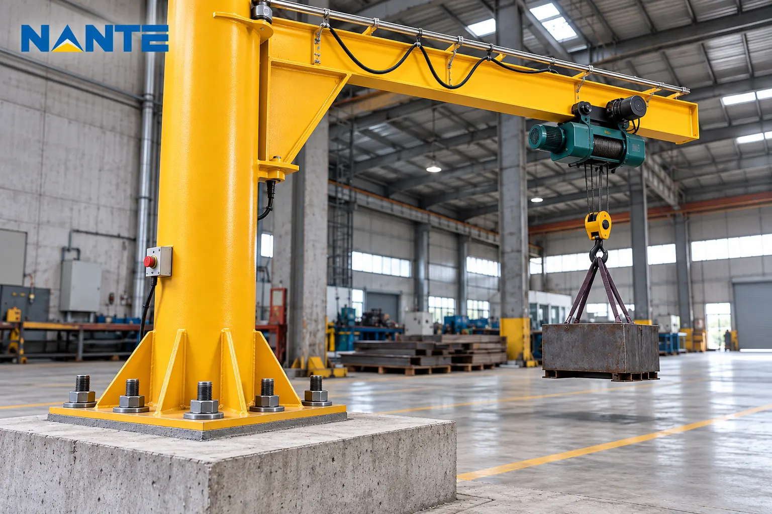
Start With the Crane Load Path
Identify the Support Configuration
A free-standing jib transfers loads through its mast, base plate, anchors, concrete, and supporting soil. A wall-mounted or column-mounted jib transfers them into the building structure instead. The support decision therefore comes before footing dimensions.
Confirm the configuration, rated load, maximum trolley radius, boom geometry, rotation range, hoist and trolley weights, mast and boom weights, base-plate layout, and support elevation. The jib crane product range illustrates why these details vary by configuration.
For a preliminary calculation, request a dimensioned general arrangement and a reaction schedule for the proposed crane. The jib crane capacity calculation addresses rated load and working radius; a foundation review must go further and follow those loads through the support.
Define the Governing Load Cases
Check the trolley at its maximum permitted radius and the boom at positions that produce the most unfavorable reaction in each foundation axis. Include unloaded or partially loaded cases where they may govern anchor tension or stability.
The engineer must establish the applicable operating, test, wind, seismic, and other project load cases and combinations. Dynamic allowances should come from the equipment data and governing design criteria. Do not apply an arbitrary percentage to every force and call it a design reaction.
Calculate Vertical and Horizontal Loads
Vertical Load at the Jib Crane Base
For an initial static estimate, add the lifted load, hoist and trolley weight, boom and mast weight, and other components supported by the foundation:
V = Wload + Whoist/trolley + Wboom + Wmast + Wother
This sum is the vertical load delivered by the crane before any specified dynamic effects. Keep component locations as well as weights: the mast may act close to the centerline, while the lifted load acts out on the boom. Both add to vertical force, but they create different overturning effects.
Foundation self-weight is a separate input to the overall footing stability and soil-bearing checks. It should not be hidden inside the crane reaction supplied to the foundation designer.
Horizontal Load Is a Separate Design Input
Slewing acceleration and braking, powered travel or trolley motion, load swing, manual handling, and other operating effects can produce horizontal reactions. Their magnitudes and application heights depend on the crane and its use; horizontal force cannot be inferred reliably from rated capacity alone.
Request the manufacturer’s horizontal reactions, directions, and load cases. The force may act in different foundation axes as the jib rotates. A calculation based only on downward weight can miss anchor shear and an additional overturning moment.
Calculate Jib Crane Overturning Moment
Apply Each Force at Its Actual Lever Arm
For a simplified static case with the boom along one foundation axis, the vertical-load moment about the mast base can be estimated as:
Mvertical = (Wload + Whoist/trolley) × R + Wboom × rboom + Σ(Wother × rother)
Here, R is the trolley radius from the mast centerline, and rboom is the distance to the boom’s center of gravity. A horizontal force H acting at height h can add H × h about the relevant axis. Account for its direction rather than automatically adding every horizontal effect to one scalar total.
Actual base reactions may also reflect the mast and bearing arrangement, offset connections, and multiple horizontal forces. Use the manufacturer’s reaction schedule for design.
Work Through a Static Illustration
Suppose a proposed crane has a 4,000 lb lifted load and a 600 lb hoist/trolley at a 12 ft radius. Assume an 800 lb boom with its center of gravity 6 ft from the mast and 1,000 lb of centered mast and other weight.
The estimated vertical crane load is 4,000 + 600 + 800 + 1,000 = 6,400 lb. The static moment from the eccentric vertical weights is (4,000 + 600) × 12 + 800 × 6 = 60,000 lb-ft.
If an equipment-specific load case also specifies a 300 lb horizontal force at 10 ft, acting in the direction that increases that same moment, it adds 3,000 lb-ft, for 63,000 lb-ft in this illustration. The 300 lb value is an assumed example, not a recommended design allowance. Impact factors, load combinations, and the actual support geometry remain unresolved.
Check Rotation and Reaction Envelopes
A rotating jib changes which side of the base is in compression and which anchors are in tension. Prepare reaction envelopes for both foundation axes, with maximum and minimum vertical force, horizontal shear, and moments identified by load case.
Do not combine independent maxima from incompatible operating positions without checking whether they can occur together. Conversely, a single boom position cannot represent all anchor groups or nearby slab edges.
Apply the Loads to Jib Crane Concrete Foundation Design
Check Soil, Stability, and the Concrete Load Path
The footing designer checks bearing pressure, settlement, sliding, overturning stability, concrete strength, reinforcement, and load transfer from the base plate into the footing and soil. A preliminary rigid-footing expression, q = V/A ± M/S, applies only when the assumed bearing distribution and full-contact condition are valid. It is not a universal footing-sizing formula.
Footing weight and any supported slab weight must be justified by the actual geometry and construction. Where a resultant falls outside the full-contact range, uplift or partial bearing requires an appropriate analysis. Geotechnical allowable pressures and settlement criteria must come from site-specific information.
Do Not Treat an Existing Slab as a Footing
An existing floor may be too thin, lightly reinforced, jointed, or close to an edge to resist the crane’s anchor tension and concentrated loads. Review as-built drawings and, where necessary, verify reinforcement, thickness, concrete condition, and what lies below the slab.
A separate reinforced foundation may be required. If the alternative is a building-supported jib, the question shifts to the column, its connections, and its own foundation. The existing-column structural checklist explains that distinct load path.
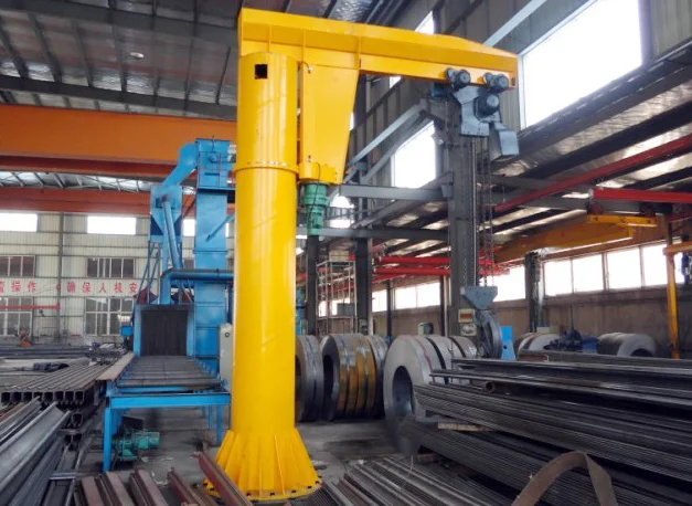
Perform the Anchor Bolt Calculation
Resolve Tension and Shear by Load Case
Overturning is resisted through a compression region under the base plate and tension in part of the anchor group. A conceptual tension-side force ≈ M/lever arm helps explain the load path, but it is not the force in each bolt. The compression location, bolt coordinates, plate stiffness, axial load, and governing load case determine the distribution.
Check anchor steel tension and shear, concrete breakout and pullout, edge and spacing effects, and combined actions under the locally adopted design provisions. In US projects, the applicable edition of ACI 318 Chapter 17 addresses anchoring to concrete. Base-plate bending, welds, grout, and any justified shear-transfer mechanism also need review.
Detail Anchors for the Actual Site
Cast-in and post-installed anchors are not interchangeable without design and installation review. Embedment, edge distance, reinforcement, cracked-concrete assumptions, drilling conditions, and installation tolerances can control a feasible solution. Specify inspection and testing requirements where applicable.
For a project-specific proposal, Nante Crane can be asked for the crane configuration and reaction information needed by the project engineer. The equipment supplier’s base details should be coordinated with the structural drawings before anchor locations or concrete are finalized.
Coordinate Design and Installation
Request a Usable Reaction Package
The project file should identify rated load, radius, rotation limits, component weights, base dimensions, anchor pattern, operating assumptions, and reactions for labeled load cases. Record whether values are service-level or factored and which dynamic effects are already included. Otherwise, the engineer may omit an effect or count it twice.
The design handoff should also define responsibility for the footing, anchors, slab modifications, and field verification. Installation planning must allow for anchor positioning, concrete strength before loading, base leveling, grouting, and inspection. The crane installation preparation guide provides related site-planning context.
FAQs
Is Rated Capacity Enough to Size a Jib Crane Foundation?
No. Two cranes with the same capacity can have different reaches, weights, base geometries, and operating reactions. The farther a lifted load is from the mast, the greater its static moment for the same weight.
Can Anchor Bolts Alone Prevent Overturning?
Anchors are one part of the load path. Their tension must pass into sound, adequately designed concrete, then through the footing to the ground. Stronger bolts do not correct insufficient embedment, edge distance, reinforcement, or footing stability.
Who Approves the Final Foundation Design?
A qualified structural engineer should verify the complete support system against the governing local requirements and site data. Manufacturer information is an essential input, but an illustrative calculation or equipment drawing is not approval to build.
Request Foundation-Relevant Crane Data
Plant engineers and project buyers should provide the required capacity, maximum radius, rotation range, proposed location, floor or footing drawings, operating conditions, and installation scope. These inputs allow Nante Crane to discuss a suitable jib configuration and the equipment information needed for structural coordination; submit the project brief through the foundation-load inquiry form.