English



How to Calculate Jib Crane Working Radius
How to Calculate Jib Crane Working Radius
Date: 2026-10-01 Share:
Jib crane working radius calculation determines how far a load can travel from the slewing axis and which parts of a work area the crane can serve. The result affects column location, foundation design, aisle clearance, load positioning, and interference control.
The basic process is straightforward: establish the boom length, locate the load centerline, project the horizontal distance, and apply the available rotation angle. The final layout should also account for the hoist, trolley, hook block, structural deflection, surrounding equipment, and required exclusion zones.

What Is Jib Crane Working Radius?
Radius, Reach, and Outreach
A jib crane radius is the horizontal distance from the crane’s slewing axis to the centerline of the suspended load. It is normally measured at the hook centerline, not at the end of the steel boom.
Jib crane reach calculation often refers to the maximum horizontal distance available to the hook. Jib crane outreach usually describes the distance from the mounting column, wall bracket, or foundation reference to the farthest hook position.
These terms can describe slightly different reference points. A purchasing specification should define the datum clearly so that engineering drawings and supplier quotations use the same measurement.
Identify the Correct Reference Point
The slewing axis is the central vertical line around which the boom rotates. For a free-standing jib crane, this axis is usually inside the support column. For a wall-mounted design, the axis may be offset from the wall face.
The working radius should be measured to the load’s center of gravity or the hook centerline, depending on the design document. Rigging length does not normally increase the crane’s structural radius, but it can change the load’s actual position and clearance requirements.
A layout drawing should show:
- Slewing axis
- Boom root and boom tip
- Trolley travel limits
- Hook centerline
- Maximum and minimum radius
- Nearby walls, machines, columns, and walkways
Jib Crane Working Radius Calculation Formula
Basic Horizontal Radius
For a level boom with a trolley, the practical radius can be estimated as:
R = E + T + H
Where:
- R = working radius
- E = horizontal distance from the slewing axis to the boom reference point
- T = trolley travel from that reference point
- H = horizontal hook or load-center offset
When the boom length is measured from the slewing axis and the trolley reaches the boom tip, the simplified calculation becomes:
Rmax ≈ L + H
Here, L is the effective boom length. The value should come from the engineering drawing rather than the overall steel length, because end plates, trolley stops, and non-load-bearing sections may reduce usable travel.
Inclined or Articulated Booms
For an inclined boom, only the horizontal projection contributes to radius. A simplified projection is:
Lh = L × cos(α)
Where:
- Lh = horizontal boom projection
- L = boom length
- α = boom angle measured from the horizontal plane
The complete layout calculation may then be written as:
R = E + (L × cos(α)) + H
Articulated jibs, knuckle booms, and offset mounting arrangements require a segment-by-segment calculation. The hook position should be evaluated at every operating configuration, especially when the load path passes near structures.
For a final design, the supplier’s approved load chart and general arrangement drawing should control the dimensions.
Jib Crane Working Radius Calculation Formula
Basic Horizontal Radius
For a level boom with a trolley, the practical radius can be estimated as:
R = E + T + H
Where:
- R= working radius
- E= horizontal distance from the slewing axis to the boom reference point
- T= trolley travel from that reference point
- H= horizontal hook or load-center offset
When the boom length is measured from the slewing axis and the trolley reaches the boom tip, the simplified calculation becomes:
Rmax ≈ L + H
Here, L is the effective boom length. The value should come from the engineering drawing rather than the overall steel length, because end plates, trolley stops, and non-load-bearing sections may reduce usable travel.
Inclined or Articulated Booms
For an inclined boom, only the horizontal projection contributes to radius. A simplified projection is:
Lh = L × cos(α)
Where:
- Lh= horizontal boom projection
- L= boom length
- α= boom angle measured from the horizontal plane
The complete layout calculation may then be written as:
R = E + (L × cos(α)) + H
Articulated jibs, knuckle booms, and offset mounting arrangements require a segment-by-segment calculation. The hook position should be evaluated at every operating configuration, especially when the load path passes near structures.
For a final design, the supplier’s approved load chart and general arrangement drawing should control the dimensions.
Rotation Angle and Jib Crane Coverage Area
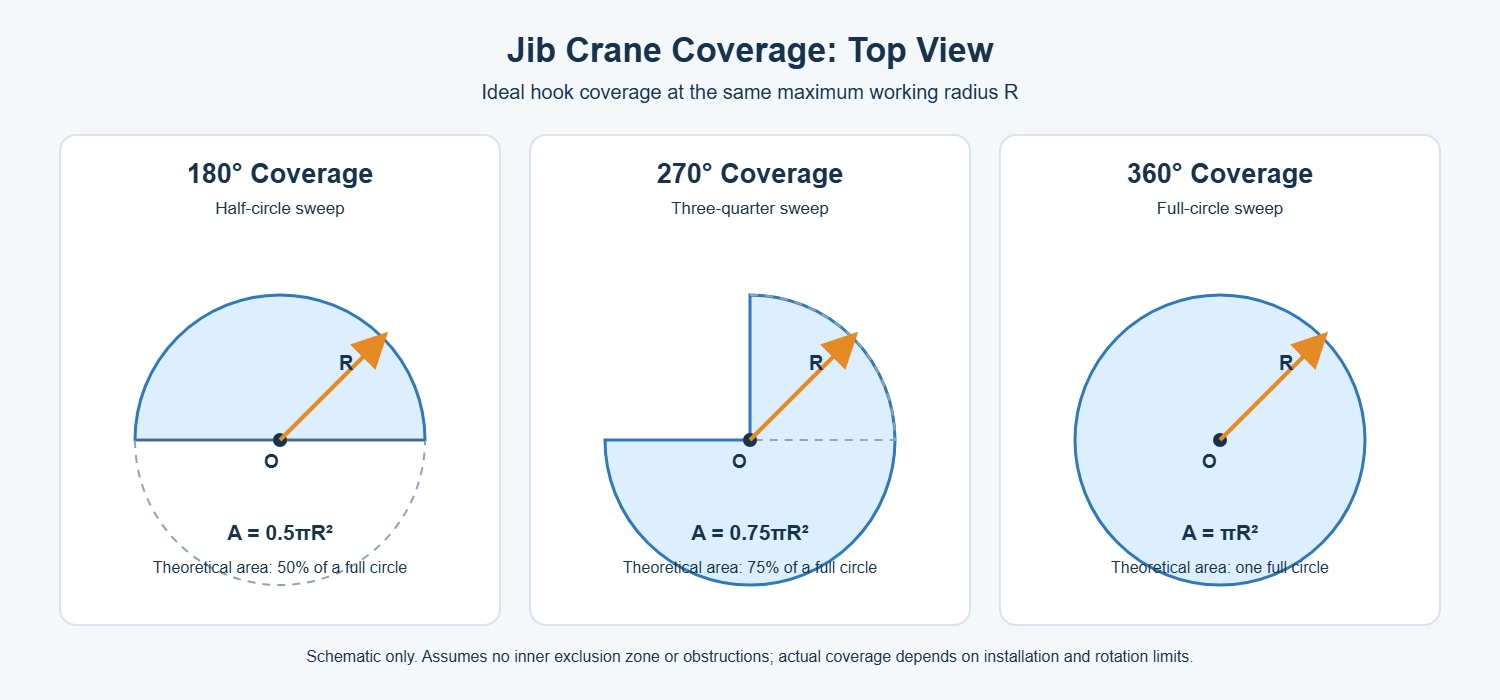
The rotation angle determines how much floor area the jib crane can serve. A larger angle increases the jib crane coverage area, even when the maximum working radius remains unchanged.
For preliminary layout planning, the theoretical coverage area can be calculated as:
Coverage area = (θ ÷ 360°) × π × R²
Here, θ is the permitted rotation angle and R is the maximum effective radius measured from the crane’s rotation center to the hook centerline.
180-Degree Coverage
A 180° jib crane serves a semicircular area on one side of its supporting column or wall. This configuration is commonly used for wall-mounted jib cranes and workstations positioned along a building wall.
The theoretical coverage area is:
A = 0.5πR²
The surrounding wall, columns, stored materials, and nearby equipment may reduce the usable area.
270-Degree Coverage
A 270° rotation provides three-quarters of a circular working area. It is useful when the crane must reach several adjacent work zones but cannot rotate through a complete circle because of structural restrictions.
The theoretical coverage area is:
A = 0.75πR²
During layout planning, the excluded 90° sector should face the wall, column, machine, or other obstruction that limits rotation.
360-Degree Coverage
A 360° jib crane can rotate around its supporting column and provides the largest theoretical coverage area for a given radius. It is generally suited to free-standing installations with sufficient clearance on all sides.
The theoretical coverage area is:
A = πR²
Full mechanical rotation does not always mean that every point inside the circle is reachable. The column, trolley travel limits, hook approach distance, and surrounding obstacles can create inaccessible zones.
Calculating the Effective Coverage Area
If the hook cannot travel all the way to the rotation center, the usable area is an annular sector rather than a complete sector. Use the following formula:
Effective coverage area = (θ ÷ 360°) × π × (Rmax² − Rmin²)
Rmax is the maximum hook radius, while Rmin is the minimum radius created by the trolley’s inner travel limit. This calculation provides a more realistic basis for equipment layout than using the boom length alone.
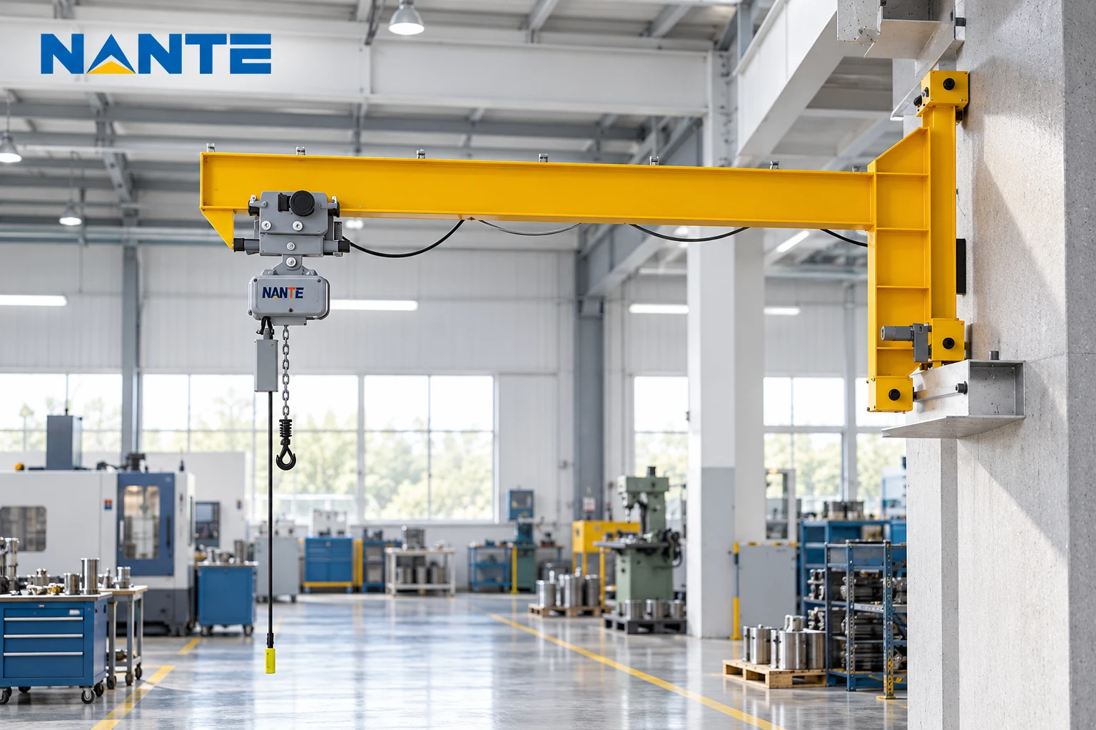
Worked Jib Crane Reach Calculation
Example Inputs
Assume the layout team has the following preliminary data:
- Distance from slewing axis to boom reference: 2 ft
- Effective trolley travel: 16 ft
- Hook centerline offset: 1 ft
- Required rotation: 270 degrees
- Inner restricted radius: 2 ft
The maximum working radius is:
R = 2 + 16 + 1 = 19 ft
The crane can therefore position the hook centerline up to approximately 19 ft from the slewing axis, subject to the manufacturer’s load chart and deflection limits.
Calculate the Effective Coverage Area
The theoretical 270-degree area without an inner exclusion zone is:
A270 = 0.75 × π × 19² ≈ 850 ft²
Including the 2-ft inner restricted radius:
A = 0.75 × π × (19² − 2²) ≈ 841 ft²
The difference is small in this example, but it becomes more important when the maximum radius is shorter or the central obstruction is larger.
The calculation does not prove that every point inside the sector is safe to lift. Floor loading, headroom, load swing, rigging geometry, and process restrictions must still be checked.
Layout Checks Before Finalizing the Radius
Obstructions and Exclusion Zones
A plan view should overlay the jib crane coverage sector on the building layout. Check for:
- Fixed machinery and storage racks
- Doors, columns, and maintenance platforms
- Overhead ducts, lights, and sprinkler systems
- Forklift aisles and pedestrian routes
- Adjacent cranes or monorails
- Areas where suspended loads are prohibited
A slightly shorter radius may provide better operational coverage if it avoids a structural column or reduces the need for restrictive rotation stops.
Foundation, Wall, and Structural Interfaces
The support arrangement must resist vertical load, overturning moment, horizontal reaction, and torque from acceleration and braking. The radius calculation helps determine the moment arm, but it does not replace a foundation or structural review.
For a free-standing crane, the base plate, anchor system, concrete foundation, and local floor capacity require confirmation. For wall-mounted and traveling designs, the supporting steelwork and building connections must be checked.
The layout package should identify who is responsible for civil work, reinforcement, anchor installation, power supply, and commissioning.
Headroom and Hook Height
Working radius is a horizontal value, but the load path is three-dimensional. The hoist may require additional headroom above the boom, while the hook and rigging require clearance below it.
A project drawing should record:
- Floor-to-boom elevation
- Maximum lifting height
- Minimum hook height
- Hoist body dimensions
- Rigging and load dimensions
- Clearance from roof steel and services
The Jib Crane Dimensions reference can help organize the dimensional information required for a technical review.
How to Specify a Jib Crane for Procurement
Data Required for a Comparable Quote
A procurement request should include more than capacity and boom length. Useful inputs include:
- Rated capacity and maximum load
- Required working radius and minimum radius
- Rotation angle: 180°, 270°, or 360°
- Lifting height and hook approach
- Duty cycle and operating hours
- Indoor or outdoor environment
- Temperature, dust, moisture, and corrosive exposure
- Power supply and control method
- Mounting type and foundation conditions
- Required standards and inspection scope
- Delivery location and installation responsibility
The Jib Crane Boom product page provides a starting point for discussing boom-based workstation lifting arrangements.
Drawings and Verification Records
Before order release, the supplier should provide a general arrangement drawing showing the slewing axis, boom length, trolley limits, hook positions, and rotation stops.
The purchasing file should also identify:
- Load chart and design assumptions
- Structural calculation responsibility
- Welding and inspection records where applicable
- Factory acceptance test plan
- Electrical and control documentation
- Installation and commissioning boundaries
- Recommended spare parts and maintenance information
The exact scope depends on the project and destination. A normalized quotation makes it easier to compare suppliers without confusing a lower equipment price with a lower total project cost.
Supplier Review and Project Application
Match the Supplier to the Layout Risk
A technically suitable supplier should be able to convert the layout inputs into a project-specific arrangement. The review should cover the crane structure, hoist and trolley selection, rotation control, foundation interface, documentation, testing, and service support.
Nante Crane presents jib crane and crane-component information for industrial buyers evaluating lifting equipment. The relevant question for a project team is whether the proposed configuration, documents, and support scope match the actual operating environment.
A supplier comparison should request the same drawing and data fields from each bidder. That approach exposes differences in usable outreach, included controls, installation assumptions, and excluded civil work.
FAQ
Is jib crane radius the same as boom length?
Not always. Radius is measured from the slewing axis to the load centerline. Boom length may start at a different reference point and may not include trolley or hook offsets.
How is jib crane coverage area calculated?
For a simple sector, use A = θ/360 × πR². If an inner restricted radius exists, use A = θ/360 × π(R² − r²). The final operational area must remove obstructions and prohibited lifting zones.
Does a larger radius always improve productivity?
No. A longer outreach can increase overturning moment, structural demand, deflection, and foundation requirements. The best radius is the shortest one that covers the required pick-and-place points with adequate clearance.
Can rotation stops be changed after installation?
Changes may affect structural clearances, electrical limits, controls, and the approved operating envelope. Any revision should be reviewed and documented by the responsible engineering team.
Prepare a Project-Specific Radius Review
A purchasing team preparing a jib crane inquiry should submit the required capacity, hook height, boom reference, desired radius, rotation angle, load dimensions, duty cycle, floor or wall conditions, and a marked-up layout.
The engineering review can then confirm the hook envelope, coverage sector, interference points, foundation inputs, and documentation scope. For a project-specific quotation and layout review, submit the marked drawing and operating data through the jib crane inquiry contact page.