English



What Determines the Span of an Overhead Crane?
Date: 2026-11-05 Share:
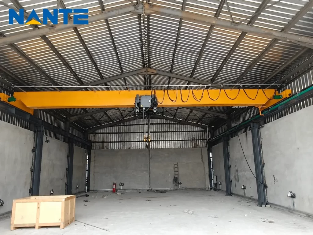
Overhead crane span is established by locating the two runway rail centerlines within the building, then verifying that the resulting geometry meets lifting coverage, clearance, and structural requirements. It is not simply the building width minus a standard allowance.
The engineering process differs between an existing runway and a new installation. Existing rails establish a measured interface that must be surveyed. A new runway allows its position to be developed around the building structure and required lifting area.
The objective is an approved span dimension supported by coordinated drawings, site measurements, and engineering checks before fabrication begins.
Define the Dimensions Before Determining Span
Separate building width from bridge crane span
For a conventional top-running crane, bridge crane span is the horizontal distance between runway rail centerlines. This follows the definition in OSHA 29 CFR 1910.179 for equipment within its scope.
A building drawing may show several different width dimensions:
- External width between outside wall faces.
- Internal clear width between inside wall faces.
- Column grid spacing between structural centerlines.
- Clear distance between projecting column faces.
- Rail centerline spacing across the crane bay.
Only the last dimension directly identifies the crane span. The others help establish where the rails can fit.
Clarify what “crane runway span” means
“Crane runway span” should be clarified whenever it appears in a tender. It may refer informally to the distance between parallel runways, while a structural drawing may use “span” for the distance between runway beam supports.
Use separate labels for crane span, runway length, and runway beam support spacing. Include dimension arrows and reference points so suppliers do not price different interpretations of the same requirement.
Establish the Building Reference Geometry
Survey the section at runway elevation
Start with a building cross-section showing the proposed rail elevation. Floor-level measurements alone may miss column brackets, roof bracing, wall projections, or services near the moving crane.
Record both inside wall faces, structural gridlines, column profiles, support locations, and fixed obstructions. Existing buildings should also be checked along the travel route because available width may vary.
The survey should identify its datum, units, date, and measurement locations. A preliminary architectural drawing is not sufficient evidence of the completed building geometry.
Diagram: building width versus overhead crane span
The following conceptual section illustrates a conventional top-running arrangement. Dimensions refer to the same horizontal measurement direction.
The offsets locate the rails. They are not equivalent to the clearance between the crane and the wall, because equipment can project outward beyond each rail centerline.
Crane Span Calculation: Convert Offsets Into Rail Spacing
Apply one consistent dimensional chain
When the internal building width and both rail offsets are known:
S = B − a − b
For an illustrative layout:
| Dimension | Assumed value |
| Internal building width, B | 80 ft |
| Left wall-to-rail-centerline offset, a | 4 ft |
| Right wall-to-rail-centerline offset, b | 5 ft |
| Preliminary crane span, S | 71 ft |
The calculation is 80 − 4 − 5 = 71 ft.
These values are hypothetical. The result establishes geometric rail spacing; it does not demonstrate that a crane or building structure is suitable.
Derive offsets rather than assuming symmetry
The left and right offsets may differ because of column geometry, existing supports, wall services, or maintenance access.
Each offset should be developed from the support arrangement and the crane’s outward equipment projection, with the necessary obstruction clearance checked separately. A fixed percentage of building width is not a reliable substitute.
Where dimensions originate from different reference points, convert them to a common datum before calculating span. Mixing wall-face measurements with column-centerline offsets produces an incorrect dimensional chain.
Determine Span Differently for Existing and New Runways
Existing runway: measure the interface first
For an existing runway, survey rail centerline spacing at multiple stations along the travel route. Also record rail elevation, alignment, rail profile, joints, support condition, and visible movement or damage.
The supplier needs the measured condition rather than a single nominal span copied from an old drawing. Variations must be assessed against the proposed crane’s agreed interface requirements.
If corrections are necessary, define the target rail geometry and correction responsibility before confirming the crane fabrication dimension. A new bridge should not be expected to compensate for an unassessed runway condition.
New runway: coordinate support position and coverage
For a new installation, rail positions can be developed alongside the building design. Start with the required lifting area and possible support lines, then check the crane envelope and structural reactions.
Moving a runway outward may improve coverage but change bracket eccentricity or connection demands. Moving it inward may simplify supports while leaving important pickup points outside the hook’s reach.
The selected span should emerge from this coordinated comparison. The Top Running Crane configuration discussion provides background on how support arrangements affect the building interface.
Check Overhead Crane Span Requirements Against Hook Coverage
Work backward from critical lifting points
Once preliminary rail positions are established, plot the required hook positions on the floor plan. Include loading stations, machine maintenance points, storage locations, and transfer interfaces.
For a conventional arrangement with the hook operating between the rail centerlines:
Usable transverse hook travel = span − left hook approach − right hook approach
Approach dimensions must come from the proposed crane drawing. They should not be borrowed from a different hoist or bridge configuration.
If a critical point is unreachable, assess the equipment arrangement and rail position together. Increasing span is only one possible response.
Check the load’s movement envelope
A reachable hook position does not prove that the load can move safely through the bay. Plot the load dimensions, rigging arrangement, and relevant obstructions along the handling route.
Keep the review focused on actual operations. A wider nominal coverage rectangle has little value if a column blocks the required transfer.
At this stage, Nante Crane product information can support configuration discussions. The official Overhead Crane category identifies available arrangements; project drawings must establish their actual dimensions and coverage.
Verify Clearance and Structural Feasibility
Check the complete moving envelope
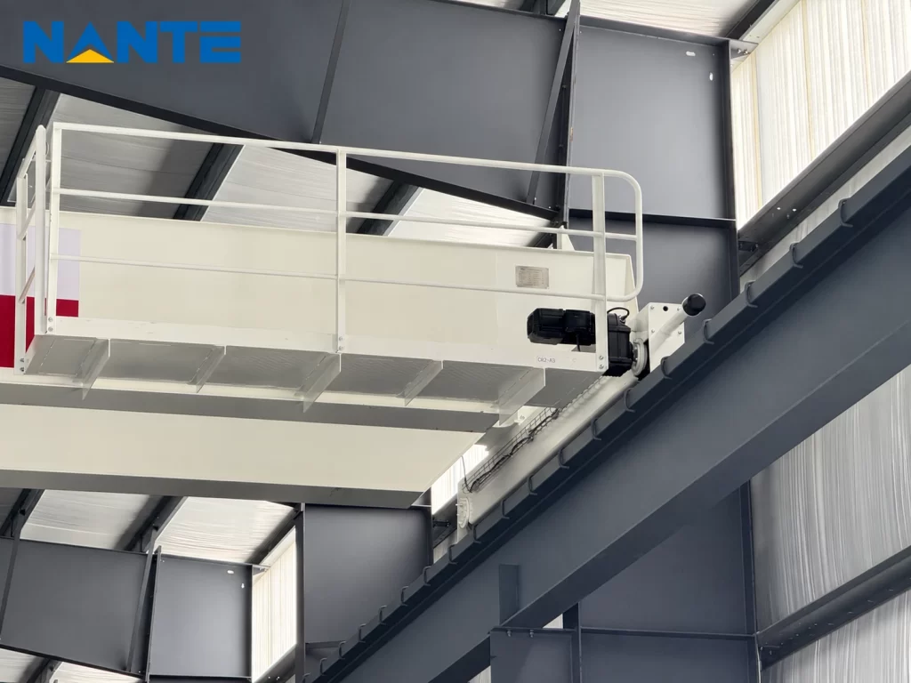
Overlay the crane’s overall dimensions on the building section, including end carriages, motors, trolley, and electrical equipment. Check the full travel route rather than one favorable cross-section.
For applicable US installations, OSHA 1910.179(b)(6)(i) requires minimum obstruction clearances of 3 inches overhead and 2 inches laterally. Project-specific maintenance, electrical, and operating requirements may require additional space.
The review should account for relevant movement and installation tolerances. Rail-to-wall offset alone cannot establish clearance compliance.
Confirm the support system can accept the design
The crane designer evaluates the proposed span together with capacity, duty, bridge weight, trolley position, and deflection requirements.
The building engineer then checks the resulting reactions through runway beams, brackets, columns, connections, bracing, and foundations. A geometry that fits the building may still require structural changes.
Where the support system is unsuitable, revise the layout or reinforcement scheme and repeat the interface checks. Span approval should follow this review rather than precede it.
Approve the Span Before Releasing Fabrication
Close the dimensional and responsibility checks
The approval package should contain:
- Surveyed building references and rail centerlines.
- Final span, rail elevation, and runway length.
- Crane envelope and hook approach dimensions.
- Critical lifting-point coverage checks.
- Wheel loads and structural interface approval.
- Runway correction and installation responsibilities.
- Agreed drawings, tolerances, and revision numbers.
The Crane Installation and service information can support scope discussions, but the quotation must identify the actual installation and verification work included.
Submit a coordinated span brief
Plant engineers and purchasing teams should provide building sections or surveys, existing runway measurements where available, capacity, lifting height, duty, critical lifting points, and delivery location. These inputs support a configuration and quotation discussion with Nante Crane through the project-specific crane span inquiry form.