English



Gantry Crane Wheel Load Calculation: An Engineering Guide
Date: 2026-10-29 Share:
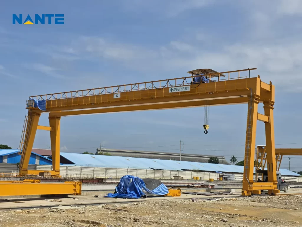
Gantry crane wheel load calculation starts with vertical force and moment equilibrium: locate the bridge weight, hoist and trolley weight, suspended load, and supporting structure weight; calculate the reaction on each rail; then distribute those reactions through the actual wheel arrangement.
Dividing total operating weight by the total wheel count gives only an average. An off-center trolley can place substantially more force on one rail, affecting wheel selection, rail supports, and foundation design.
The following method explains preliminary calculations for rail-mounted, ground-supported gantries—not rubber-tired or semi-gantry configurations.
Identify Every Gantry Crane Wheel Load Input
Bridge weight, hoist weight, and lifted load
Separate fixed and moving weights before calculating reactions:
- B:bridge girders, walkways, and fixed bridge-mounted equipment.
- T:moving hoist and trolley assembly, including equipment assigned to that assembly.
- Q:suspended load for the selected case, including applicable rigging and lifting attachments.
- Dₗ and Dᵣ:left and right leg assemblies, end carriages, and travel equipment supported locally.
Check whether the supplier’s stated crane self-weight already includes the trolley, legs, or hook block. Each item must appear once. Use actual centers of gravity rather than assuming every fixed component acts at midspan.
Use force units consistently. In US calculations, 1 kip equals 1,000 lbf; a short-ton weight equals 2,000 lbf. Metric tonnes describe mass, not kilonewtons. Record the conversion basis whenever supplier data uses another unit system.
Leg structure and the load-transfer path
The suspended load passes through the hoist and trolley into the bridge girders. The girders transfer reactions into the legs, which deliver loads through end carriages or bogies to the wheels and rails.
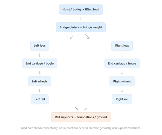
Leg and travel-unit self-weight enters the load path below the girders. A-frame geometry, rigid or articulated connections, unequal stiffness, and eccentric equipment can alter individual wheel reactions.
A side reaction is not automatically an individual leg force or wheel load.
Calculate Rail Reactions Before Wheel Reactions
Establish the geometry and assumptions
Let L be the distance between rail centerlines and x the distance from the left rail to the combined trolley and suspended-load resultant. Let xᵦ locate the bridge-weight resultant from the left rail.
For this preliminary vertical-only model, assume two rail support lines, no cantilever operation, and local dead weights acting over their respective rails. Then:
Rₗ = B(L − xᵦ)/L + (T + Q)(L − x)/L + Dₗ
Rᵣ = Bxᵦ/L + (T + Q)x/L + Dᵣ
The equilibrium check is:
Rₗ + Rᵣ = B + T + Q + Dₗ + Dᵣ
If trolley and suspended-load resultants have different transverse positions, calculate their moment contributions separately. For overhangs or other arrangements, establish equilibrium from the actual geometry instead of extending these assumptions uncritically.
Distribute reactions through the wheels
When equal sharing is justified, a rail-side reaction R carried by n wheels gives P = R/n. Equal sharing requires supporting geometry and a suitable load-sharing mechanism; wheel count alone does not establish it.
For a two-wheel group with wheelbase b, a centered vertical resultant R plus a signed moment M about the group midpoint gives:
P₁ = R/2 + M/b
P₂ = R/2 − M/b
This local expression assumes two contacting supports and includes all relevant group weights in R and M. Multiwheel frames may require stiffness analysis, while articulated equalizers require their own lever-arm calculations.
Specify the End Carriage layout early. Increasing wheelbase reduces the moment-induced difference in this two-support model, but it does not reduce R/2 when the applied moment is zero.
Likewise, a wider leg footprint cannot justify equal wheel loads without checking where the leg forces enter the travel frame.
Worked Example: Gantry Crane Maximum Wheel Load
Compare three static trolley positions
Consider hypothetical inputs, not a product specification: B = 30 kip, T = 6 kip, Q = 40 kip, Dₗ = Dᵣ = 8 kip, L = 60 ft, and xᵦ = 30 ft. Assume two equally loaded wheels per rail.
For the loaded trolley 6 ft from the left rail:
Rₗ = 15 + 46 × 54/60 + 8 = 64.4 kip
Rᵣ = 15 + 46 × 6/60 + 8 = 27.6 kip
Each left wheel carries 32.2 kip, and each right wheel carries 13.8 kip. The reactions total 92 kip, matching all applied weights.
| Static case | Each left wheel | Each right wheel |
| Loaded trolley at x = 6 ft | 32.2 kip | 13.8 kip |
| Loaded trolley at x = 30 ft | 23.0 kip | 23.0 kip |
| No payload, trolley at x = 6 ft | 14.2 kip | 11.8 kip |
The largest illustrated reaction is 32.2 kip, not the 23.0-kip overall average. The lowest illustrated reaction is 11.8 kip, showing why the lighter side of the loaded crane does not necessarily govern minimum wheel load.
Build the governing design envelope
These results exclude dynamics, wind, horizontal actions, and structural load factors. The gantry crane maximum wheel load must come from the governing project load cases, not this static example alone.
Evaluate both trolley travel limits, relevant intermediate positions, loaded and unloaded operation, and applicable test, parked, and environmental conditions.
Identify whether reactions are static, dynamically amplified, or factored. Avoid applying an additional impact factor to values that already include it.
Hoisting dynamics and travel acceleration are different actions. Outdoor wind can also produce overturning moments that redistribute vertical reactions.
The calculation package should identify which actions occur together and which are separate cases, rather than applying one blanket percentage to every weight and calling the result the design load.
A zero or negative calculated compression requires review of wheel lift-off, stability, and restraints. Ordinary wheel-to-rail contact cannot transmit tension.
Turn Gantry Crane Rail Load into Interface Requirements
Separate wheel force from contact pressure
Supplier terminology sometimes uses gantry crane wheel pressure to mean vertical force per wheel. Confirm the units: kip or kN indicates force; psi or MPa indicates stress. Wheel load alone does not determine wheel–rail contact stress.
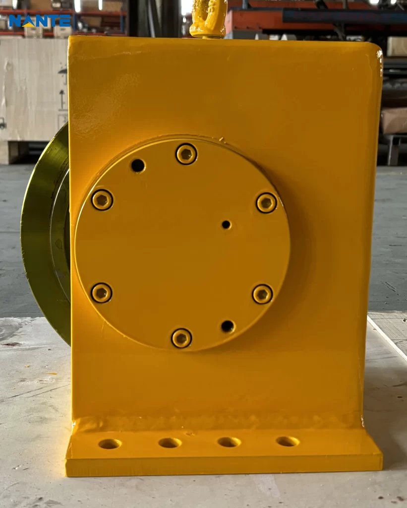
Wheel diameter, tread geometry, rail-head profile, materials, and operating duty also matter. Review the Crane Wheel and bogie arrangements against the calculated reactions rather than treating a larger wheel as an automatic solution.
Preserve simultaneous loads and wheel spacing
Gantry crane rail load is a moving set of concentrated wheel forces, not a uniform load obtained by dividing crane weight by rail length. Rail bending and support reactions depend on adjacent wheels, spacing, and crane position.
Nante Crane lists gantry cranes and associated travel components. Its double-girder gantry crane page provides configuration context, but project-specific reactions still require confirmed geometry and weights.
Coordinate the selected Crane Rail with pads, clips, joints, anchorage, support stiffness, and foundation conditions.
Do not combine unrelated wheel maxima into a supposedly simultaneous case. Foundation bearing pressure also requires the civil engineer’s structural and ground model.
Verify the Supplier’s Calculation Package
Request traceable engineering evidence
Before releasing rails or foundations for construction, request:
- A general arrangement with numbered wheels, rail gauge, wheelbase, bogie spacing, and trolley limits.
- A weight schedule identifying centers of gravity and all included accessories.
- Maximum and minimum wheel reactions, governing cases, and simultaneous reaction patterns.
- Horizontal forces, wind assumptions, duty inputs, and declared dynamic and load factors.
- Wheel, bearing, end-carriage, and rail-interface checks, plus calculation revision status.
For US projects, the responsible engineers should agree on applicable crane criteria and locally adopted structural requirements. A supplier’s general standards statement does not establish project compliance.
At procurement, agree on drawing approval responsibilities and the release point for final reactions. Request relevant material, inspection, and factory-test records, while recognizing that a successful lifting test does not independently verify the site’s buried foundation or soil capacity.
Keep those responsibilities explicit in the purchase specification.
The related gantry crane capacity calculation guide addresses the lifting-capacity brief; wheel reactions remain a separate interface deliverable. Installation and commissioning records should confirm the approved wheel layout and rail geometry.
Frequently Asked Questions
Does adding wheels always reduce the maximum load?
Not proportionally. Additional wheels help only when the structure or equalizing system distributes force as intended. Their spacing also changes how neighboring loads act on rail supports.
Can a preliminary calculation approve an existing foundation?
No. Preliminary reactions support feasibility discussions. Existing foundations need verified construction information, condition assessment, ground data, and checks using the agreed design load cases.
Prepare a Wheel-Load Engineering Inquiry
Submit the layout and operating brief
Nante Crane’s published service scope includes design consultation. Purchasing teams can request a project-specific configuration review by providing capacity, span, lifting height, trolley approach, duty, indoor or outdoor conditions, and available rail or foundation drawings. Include any documented wheel-load limit and its calculation basis through the gantry crane technical inquiry form.