English



How to Choose the Right Overhead Crane Span and Lifting Height
How to Choose the Right Overhead Crane Span and Lifting Height
Date: 2026-09-04 Share:
Selecting an overhead crane is a geometry decision before it is a capacity decision. The correct span must cover the working envelope without forcing the runway into unsuitable columns or walls. The correct lifting height must place the hook where loads are picked up, moved, and set down while retaining clearance for the bridge, trolley, rigging, and building services.
Dimensional errors can reduce usable floor area or create collision risks. The process below supports a layout drawing and comparable quotations.
Start With the Building and Runway Geometry
Separate building width from crane span
Crane span is normally the centerline-to-centerline distance between the two runway rails. It is not automatically the building width, bay width, or distance between column faces. The runway gauge must fit the end-carriage design, rail seats, maintenance access, and structural tolerances.
Measure these dimensions on the as-built drawing and confirm them on site:
- Inside distance between columns or other fixed supports.
- Runway rail centerlines and rail elevations.
- Bay length and the full longitudinal travel path.
- Roof trusses, services, maintenance platforms, and floor elevations at pickup points.
For a practical starting value, the required span equals the runway gauge needed by the crane plus the rail-seat and structural clearances specified by the designer. The final value should come from a plan and section drawing, not a tape measure alone.
Define runway distance and end approach
Runway distance is the longitudinal travel length along the rails. It determines whether the hook can reach all workstations, not how wide the crane is. Identify the farthest required pickup and set-down points, then add the end approach needed for the end carriage, buffers, maintenance access, and any restricted zone.
A short runway can leave workstations outside the hook envelope; a long runway can conflict with fire separation, expansion joints, or another crane. Show rail stops, buffers, access ladders, and adjacent-crane limits.
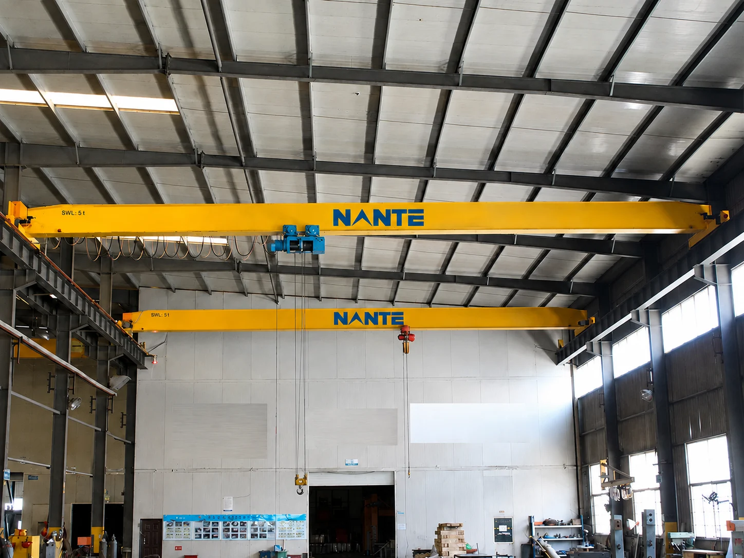
Perform an Overhead Crane Span Calculation
Map the usable working area
Plot load centers rather than machine footprints. Mark storage, process equipment, doors, inspection stations, and drop zones; record maximum load dimensions and rigging at each point.
The bridge must cover every load center with a positioning margin. State minimum hook coverage at each station; spanning the building is not enough if a process line is missed.
Check hook approach in both directions
Hook approach is the distance from the hook centerline to a wall, column, runway end, or other obstruction. Trolley position controls side approach; bridge and end carriage control end approach. Show both on the general arrangement.
Use the most restrictive approach and include the hook block, load, slings, beams, and expected sway. Compact hoists or alternative end carriages may improve approach, but the crane engineer must confirm the effect.
Use a section drawing, not only a plan
The simplified diagram below identifies dimensions for the quotation drawing:
Roof / services
building clearance for overhead crane
|<——->|
runway rail ===================== runway rail
<— span —>
[ bridge ]
[trolley]
|
crane hook
|
<— lifting height —>
|
floor/load
<———– runway distance ———–>
|<– end approach –>| |<– side hook approach –>|
State whether lifting height is measured from the finished floor, rail top, or another datum; mixed datums make offers appear different.
Determine Overhead Crane Lifting Height
Define the required hook elevation
Overhead crane lifting height is the vertical distance from an agreed datum to the hook’s highest working position. Derive it from the tallest load, fixture, or vehicle, plus rigging and clearance.
The minimum required lift can be expressed as:
Required lift = highest set-down elevation – pickup datum + rigging and clearance allowance
This differs from nominal rope travel: extra rope does not solve a trolley or bridge headroom conflict.
Calculate crane hook height from the top down
Start at the roof underside or lowest obstruction. Subtract building clearance, rail/support depth, bridge depth, trolley/hoist envelope, and maintenance space. The remainder is the practical top-hook height.
Compare top-hook height with set-down elevation. If the margin is small, evaluate low-headroom hoists, another girder arrangement, a raised runway, or a lower datum. Check hook-block dimensions and reeving.
Include rigging and load-control needs
Slings, beams, C-hooks, magnets, and fixtures consume vertical space. Record the longest rigging and tallest load; use the rotated envelope for loads turning or passing through doors.
Verify Building Clearance for Overhead Crane
Identify fixed and dynamic obstructions
Building clearance includes static rail space and the dynamic envelope from deflection, trolley movement, sway, festoon, buffers, and maintenance. The structural engineer should verify deflection, reactions, and connections for selected wheel loads.
Keep services outside the crane envelope. If relocation is impossible, show the obstruction and specify a physical or control restriction. Check the worst load position and bridge travel.
Coordinate structural and regulatory reviews
Have runway steel, columns, rail clips, and foundations reviewed for wheel loads and duty class. Requirements may include local rules, OSHA, ASME B30.2, CMAA, EN, or other jurisdiction-specific standards; name the governing edition in the purchase specification.
Match Span and Height to Crane Configuration
Compare single girder and double girder layouts
Single girder cranes can be a strong fit where capacity, span, hook height, and duty cycle are moderate and headroom is limited. A Single Girder Crane page can be used as a reference for a compact bridge and low-headroom hoist arrangement.
Double girder layouts provide a different trolley and bridge envelope that may suit heavier loads, longer spans, or higher duty requirements. Review a Double Girder Crane arrangement when walkway, maintenance access, or a larger lifting mechanism changes the top-hook calculation.
Select the hoist around the load path
Hoist selection affects side approach, hook block height, lifting speed, and maintenance access. A wire-rope solution may be appropriate for the planned duty and lift, but the specification should confirm rope reeving, drum position, hook type, and headroom. The Wire Rope Hoist product link is a starting point for component review; the final model must follow the load spectrum and duty calculation.
Build a Procurement-Ready Specification
Put dimensional inputs in one schedule
An RFQ should include:
- Rated capacity, maximum lifted load, load spectrum, and duty class.
- Span, runway distance, rail size, rail elevation, and support details.
- Required top-hook and low-hook elevations, pickup/set-down points, and approaches.
- Building obstructions, environment, indoor/outdoor use, power, controls, speeds, braking, festoon, and access.
- Applicable codes, inspection hold points, test documents, manuals, spares, installation, and commissioning scope.
The buyer can use Overhead Crane Specifications as a product-category reference, then attach the project drawing and dimensional schedule to each bid.
Normalize quotations before comparing price
Ask every supplier to identify runway work, structural modifications, controls, testing, freight, installation, training, warranty, spares, and exclusions. Require a marked-up arrangement showing span, hook height, approaches, wheel loads, and clearances.
Reject offers that meet capacity but leave a station outside the hook envelope. Prices are not comparable when runway steel, modifications, commissioning, or documents are omitted.
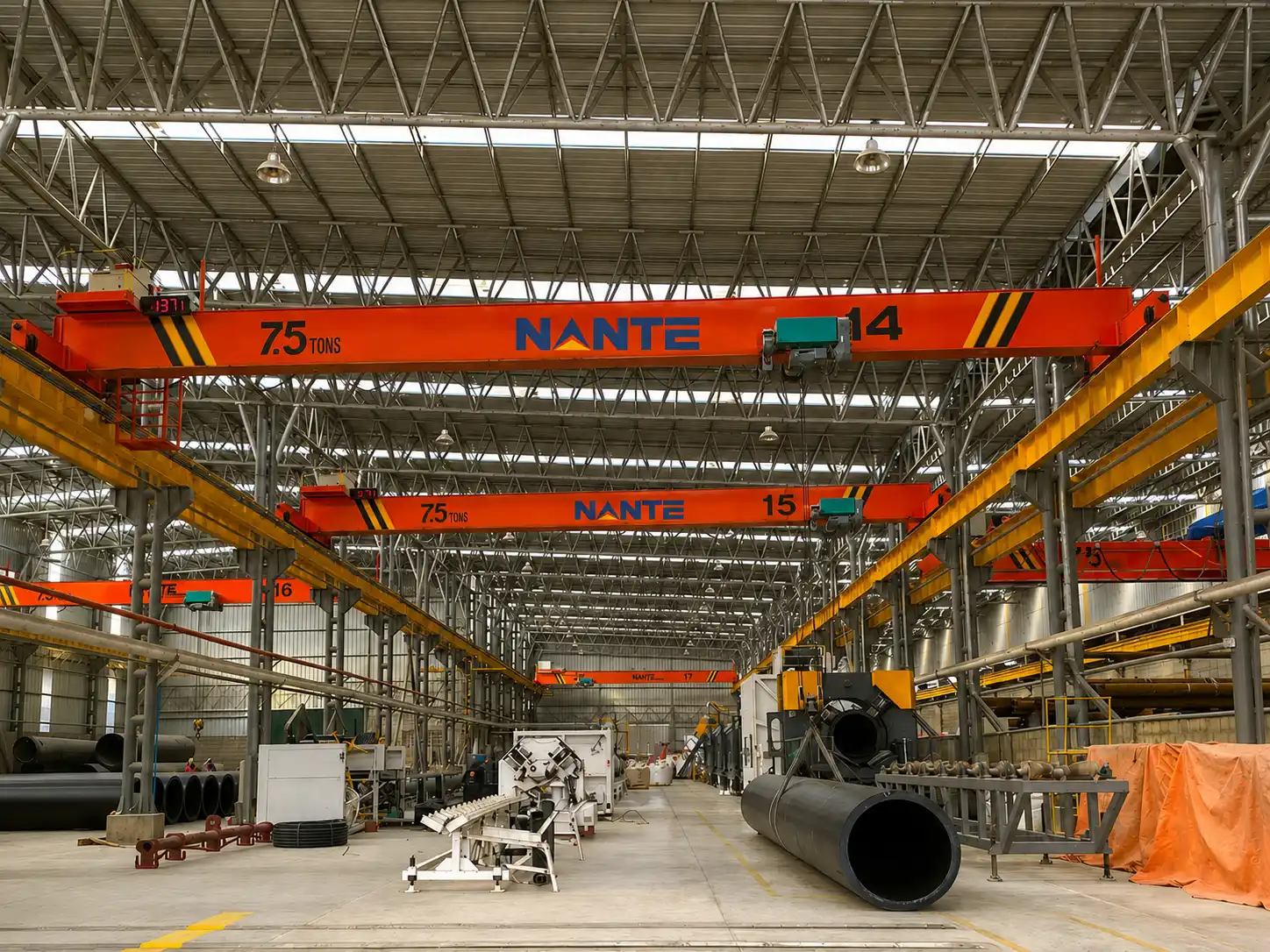
Validate the Design With Nante Crane
Use published ranges as a screening reference
Published Nante Crane pages provide comparison points: single girder lists 1-20 t, 3-30 m lifting height, and 5-30 m span; double girder EOT lists 5-63 t, 3-30 m, and 5-40 m. These ranges are not substitutes for project calculations. The pages reference FEM, CMAA, EN ISO, and GB design codes.
For a layout review, the project owner can share plan and section drawings with Nante Crane, plus capacity, duty class, hours, load envelope, hook elevations, obstructions, power, destination, and installation scope. These inputs support a configuration and documentation review before quote comparison.
Frequently Asked Questions
How do buyers determine crane span?
Determine span from runway rail centerlines and hook coverage at every station. Confirm it against column spacing, end-carriage dimensions, approaches, tolerances, and the final arrangement.
What is the difference between lifting height and crane hook height?
Lifting height is the specified travel range; crane hook height is actual elevation from a defined datum. The quotation should state the datum and top/low hook positions.
How much building clearance is needed for an overhead crane?
There is no universal number. Clearance depends on bridge, trolley, hoist, runway, deflection, sway, services, maintenance, and local rules. Show and check it in the section drawing.
Can a low-headroom hoist increase usable lifting height?
It can reduce the hoist envelope above the hook, but trolley geometry, bridge depth, runway elevation, and rigging determine the result. Recalculate the section before selection.
Send the Dimensions for a Technical Review
Share project inputs once
The fastest route to a comparable recommendation is a dimensioned plan and section showing span, runway distance, rail elevation, obstructions, hook approaches, pickup/set-down elevations, capacity, duty class, and destination. The project team can submit those inputs for a configuration and quotation review through Contact Nante Crane.