English

Common Electrical Failures in Crane Control Panels
Common Electrical Failures in Crane Control Panels
Date: 2026-06-04 Share:
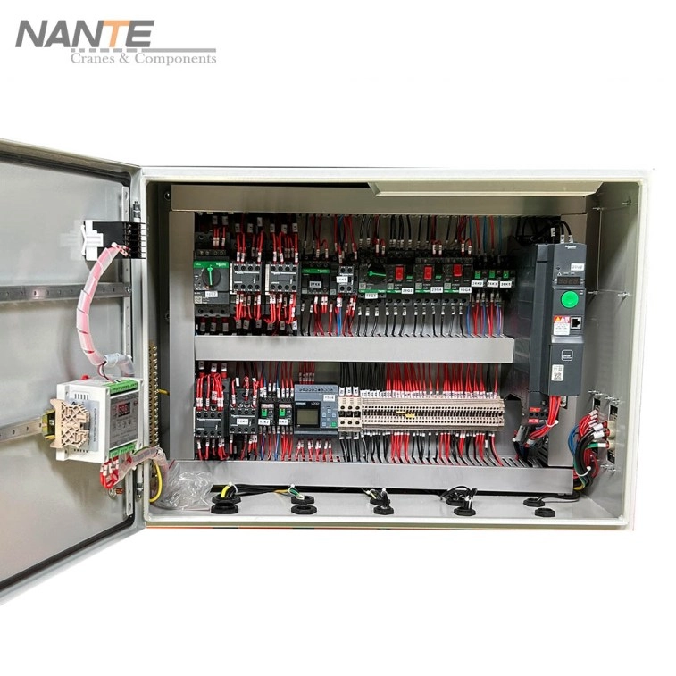
Crane Control Panel Failures can stop lifting, trolley travel, bridge travel, braking, and safety interlock functions. In many cases, crane electrical cabinet failures are not caused by one single damaged part, but by loose wiring, unstable voltage, relay wear, PLC signal loss, inverter alarms, or heat buildup. Effective overhead crane control system troubleshooting starts with clear diagnostics, verified repair methods, and preventive maintenance records.
Why Crane Control Panel Failures Matter in Daily Crane Operation
A crane control panel connects operator commands with hoisting, long travel, cross travel, braking, limit protection, and motor control. When the panel fails, the crane may stop suddenly, move irregularly, respond slowly, or fail to start.
A control panel problem should not be treated as only a cabinet issue. It may involve the incoming power supply, control voltage, pendant station, remote control, limit switches, brake circuit, inverter, PLC input/output module, contactor, relay, or grounding system.
Recognized overhead crane safety rules also emphasize inspection and maintenance of operating mechanisms, control systems, limit switches, and electrical apparatus. Frequent inspections may be required from daily to monthly intervals, while periodic inspections may be required from 1 to 12 months depending on service conditions.
Common Signs of Crane Electrical Cabinet Failures
The first step is symptom collection. A technician should record what happened, when it happened, whether the fault is repeated, and whether it appears during no-load or loaded operation.
Common warning signs include:
- The crane does not start after power-on.
- Hoisting, trolley, or bridge movement is delayed.
- Circuit breakers or fuses trip frequently.
- The cabinet has a burning smell or hot surface.
- The inverter shows repeated alarm codes.
- Relays click, but the crane does not respond.
- PLC inputs or outputs appear unstable.
- Emergency stop, overload, or limit circuits remain active.
- Pendant or remote commands respond intermittently.
No Power or Intermittent Power Supply
No-power faults often come from the main disconnect, breaker, fuse, transformer, phase loss, weak control voltage, loose terminal, or damaged cable.
The diagnostic sequence should begin with incoming voltage, phase balance, control transformer output, grounding, and cabinet terminal tightness. Random component replacement should be avoided before confirming the power path.
Control Signal Is Present but Crane Does Not Move
If the command signal is present but the crane does not move, the fault may be downstream. Common points include PLC outputs, relays, contactor coils, brake release circuits, inverter enable signals, motor cables, or travel limit interlocks.
The correct method is to trace the circuit from input command to final actuator. This prevents unnecessary replacement of expensive components.
Crane PLC Faults: How to Diagnose Control Logic Problems
Crane PLC faults are often misunderstood. The PLC itself may be working correctly, while the actual problem comes from a field device, damaged cable, weak control voltage, electrical noise, or failed output relay.
A PLC should be checked as part of a complete signal chain, not as an isolated black box.
Common Causes of Crane PLC Faults
Typical causes include:
- Unstable control voltage
- Missing input from limit switches
- Failed sensor or pushbutton contact
- Loose PLC terminal wiring
- Output module failure
- Incorrect interlock condition
- Communication interruption
- Electrical interference from power circuits
- Parameter or logic changes after maintenance
PLC Troubleshooting Checklist
Use a structured checklist:
- Check PLC power and error indicators.
- Confirm whether input lights change when switches are operated.
- Confirm whether output lights activate after a valid command.
- Compare actual I/O status with the electrical drawing.
- Inspect field wiring between devices and PLC terminals.
- Record alarms before resetting.
- Check shielding and grounding if signals are unstable.
- Do not change PLC logic before hardware faults are ruled out.
Inverter Faults in Crane Control Panels
Inverter Faults Caused by Power and Load Problems
Inverter faults often affect speed control, smooth starting, deceleration, and braking. Common alarm conditions include overcurrent, overvoltage, undervoltage, overload, overheating, and communication failure.
Power-side causes include weak incoming voltage, phase imbalance, poor grounding, shorted motor cable, or incorrect protection settings. Load-side causes include overloaded lifting, mechanical resistance, brake dragging, improper acceleration time, or incorrect motor parameters.
Inverter Fault Troubleshooting Checklist
A practical inverter inspection should include:
- Record the exact fault code before reset.
- Check incoming voltage and phase condition.
- Inspect motor cable insulation and grounding.
- Confirm motor data and inverter parameters.
- Check whether the brake releases before motor torque rises.
- Inspect the cooling fan and ventilation path.
- Test operation under no-load and controlled-load conditions.
- Restore only verified parameters after repair.

Relay Failures and Contactor Problems
Relays and contactors operate repeatedly during crane movement. Because they switch control and power circuits, they are common wear points in crane electrical cabinets.
Repeated relay failures usually indicate a deeper cause, such as unstable voltage, coil overload, vibration, dust, moisture, or a shorted control circuit.
Relay Failures in Control Circuits
Common relay problems include coil burnout, contact oxidation, sticking contacts, loose sockets, incorrect coil voltage, and poor terminal contact.
A clicking relay does not always mean a healthy circuit. The contact may be mechanically moving but electrically failing under load. Voltage testing and continuity testing are both necessary.
How to Repair Relay and Contactor Failures
Repair should begin with isolation and verification. Damaged relays and contactors should be replaced with parts matching the correct coil voltage, current rating, contact type, and duty requirements.
After replacement, the controlled circuit must be tested. If the same relay fails again, the root cause may be wiring damage, voltage fluctuation, high inrush current, heat, or vibration.
Control Panel Overheating: Causes, Risks, and Prevention
Control panel overheating can accelerate insulation aging, weaken electronic components, deform terminals, cause nuisance trips, and shorten service life. Heat is especially serious when inverters, transformers, contactors, and power supplies are installed in compact cabinets.
Crane safety rules also require electrical apparatus such as controller contactors, limit switches, and pushbutton stations to be checked for pitting or deterioration during periodic inspection.
Main Causes of Control Panel Overheating
Major causes include:
- Loose terminals increasing resistance
- Overloaded circuits
- Failed cabinet fan
- Blocked air filter
- Dust accumulation
- High ambient temperature
- Undersized conductors
- Frequent start-stop operation
- Poor inverter heat dissipation
- Moisture or corrosion inside the cabinet
Control Panel Overheating Troubleshooting Checklist
Use this checklist before restarting normal operation:
- Check cabinet surface temperature and internal hot spots.
- Look for discolored wires or hardened insulation.
- Inspect terminal marks and signs of arcing.
- Confirm fan operation and clean filters.
- Measure load current against rated current.
- Tighten terminals according to maintenance procedures.
- Separate heat-generating devices where possible.
- Improve cabinet sealing if dust or moisture enters.
- Record repeated overheating locations.
Overhead Crane Control System Troubleshooting Process
Overhead crane control system troubleshooting should follow a clear process. The goal is to isolate the fault path, confirm the cause, repair the defect, and test the crane safely before returning it to operation.
Before adjustments or repairs, controllers should be placed in the off position, the main or emergency switch should be opened and locked, and warning signs should be placed where visible.
Step 1: Confirm the Fault Symptom
Identify whether the failure affects lifting, lowering, cross travel, long travel, braking, safety limit, remote control, pendant control, or the whole crane.
A clear symptom saves troubleshooting time.
Step 2: Check Power Supply and Protection Devices
Check the main power supply, breaker, fuse, phase sequence, control transformer, emergency stop circuit, and grounding.
Many cabinet faults come from unstable power rather than damaged internal devices.
Step 3: Inspect Input Devices and Safety Interlocks
Check pendant buttons, remote receiver output, emergency stop contacts, limit switches, overload protection, door interlocks, and travel limits.
A single open safety circuit can prevent normal operation.
Step 4: Trace Output Components
Follow the output side step by step: PLC output, relay, contactor, inverter enable, brake coil, motor cable, and motor terminal.
If the signal disappears at one point, the fault range becomes much smaller.
Step 5: Test After Repair
After repair, test without load first. Then perform controlled functional testing according to site rules and equipment requirements.
Operational testing should verify hoisting, lowering, trolley travel, bridge travel, limit switches, locking devices, and safety devices before normal use resumes.
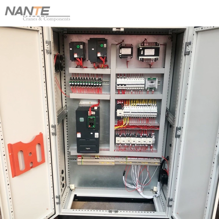
Crane Control Panel Manufacturer and Supplier Support from Nante Crane
Nante Crane provides crane control panels for hoisting control, long travel control, and whole crane control. Its crane control panel page describes the control panel as a core crane component that sends action signals to mechanisms after receiving instructions, and also lists options such as anti-sway, automation crane, IoT, and data logger services. Nante Crane also provides industrial cranes, offshore cranes, electric hoists, crane travel units, mobile power supply systems, and crane components, with product and service experience across 50+ countries and regions.
FAQ
What are the most common Crane Control Panel Failures?
Common failures include loose wiring, relay failures, contactor wear, inverter faults, crane PLC faults, overheated components, damaged safety circuits, poor grounding, moisture, and unstable control voltage.
How can crane PLC faults be diagnosed?
Crane PLC faults should be diagnosed by checking PLC power, input signals, output signals, field wiring, interlocks, control voltage, communication status, and alarm history before changing logic.