English

Why Is a Unipole Conductor Rail Preferred for Long-Travel Crane Systems?
Why Is a Unipole Conductor Rail Preferred for Long-Travel Crane Systems
Date: 2026-03-13 Share:
Long-travel cranes need a trustworthy long-travel crane power supply system. This system keeps operations smooth over long distances without stops. Unipole conductor rail for long-travel cranes works well as an efficient single-pole conductor rail for cranes solution. The insulated single-pole design cuts voltage drop. It handles high current loads up to 1600A. It also makes installation simpler than multi-pole options. This system fits gantry cranes, port equipment, and heavy-duty industrial setups. It improves reliability and lowers maintenance needs. In this detailed guide, we look at its structure, benefits, applications, technical parameters, voltage drop issues, and best practices. These help engineers and procurement teams pick the best system.
Understanding Unipole Conductor Rails: Core Structure and Design Principles
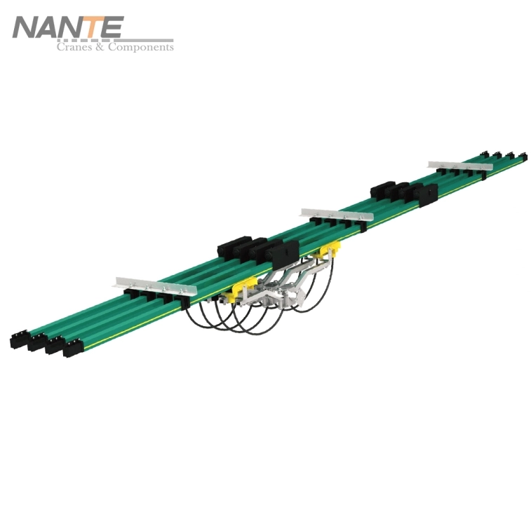
Unipole conductor rails, also called single-pole insulated systems, supply mobile power through separate insulated poles. Each phase runs on its own rail. This setup allows flexible pole arrangements to match crane needs.
High-purity conductors—copper (99.9999% purity, T3 level) or aluminum—sit inside tough PVC housing. The housing uses low calcium powder. This keeps the shape stable and makes it last longer. Mobile collector shoes have copper-graphite brushes. These brushes keep sliding contact steady. They ensure steady electrical flow while the crane moves.
The modular design works great on long straight runways or gentle curves common in crane work. It gives steady power to hoists, trolleys, and travel motors with very few breaks. (Suggested image: Cross-section diagram of unipole conductor rail showing conductor, PVC insulation, and collector shoe engagement.)
Single-Pole Conductor Rail Design
The single-pole setup has separate rails for each phase. It also includes a protective earth (PE) rail. This makes it possible to adjust pole numbers, like three-phase three-wire or four-wire systems.
Standard bar lengths come as 4m or 5.8m. Bolted joints provide strong connections. Conductors give great conductivity and low resistivity. The high-insulation PVC housing guards against accidental touch. It also lengthens service life.
Modularity allows simple expansion. It adapts easily to different crane layouts.
Key Differences Between Unipole and Enclosed Conductor Rails
Unipole rails feature individual poles with basic insulation. This gives flexibility and high current support. Enclosed rails combine multiple poles inside a protective housing. They offer better resistance to dust, water, and debris.
Unipole delivers higher current capacity (up to 1600A in copper models). It suits long spans better with lower voltage drop. Enclosed systems (typically 50-240A) perform well in tough environments. However, they have more parts and higher costs.
Unipole brings cost-effectiveness, easier installation, and the ability to replace single rails if damaged.
| Feature | Unipole Conductor Rail | Enclosed Conductor Rail |
| Structure | Single-pole, open/individual design | Multi-pole in fully protective housing |
| Current Capacity | 250A–1600A (copper/aluminum models) | Typically 50A–240A |
| Environmental Protection | Basic insulation, suitable for moderate conditions | Enhanced dust/water/debris resistance |
| Installation Ease | Modular, quick jointing, fewer parts | More components, but snap-fit options |
| Best For | Long-travel, high-current cranes | Harsh, contaminated indoor/outdoor |
| Cost | Lower overall | Higher due to enclosure |
| Voltage Drop Performance | Excellent over long distances | Good but limited by capacity |
(Suggested image: Side-by-side comparison of unipole and enclosed rail profiles.)
Electrical Insulation and Safety Features
High-quality PVC insulation stops accidental contact. It meets finger-safe standards. Phase separation and dedicated PE rails improve electrical safety.
Systems follow international standards such as EN 60204 and VDE for crane use. Reinforced plastic joint boxes and end feeds increase durability. They lower risks during high-voltage work.
Advantages of Unipole Conductor Rails for Long-Travel Crane Operations
Unipole rails work very well on runways longer than 100-200m. They reduce the number of joints. They also handle high-speed and high-load travel.
Benefits cover strong current handling, flexible layouts, and less downtime thanks to reliable contact.
Superior voltage drop performance over extended distances
High amperage for demanding crane motors
Flexible for straight or mild curve paths
Lower transmission losses compared to alternatives
Benefits for Long-Distance Crane Travel
Unipole handles extended runways without too many power feeds. It allows high-speed work with steady power. This suits heavy-load movement in large facilities.
It raises productivity. It cuts interruptions during big crane tasks.
Minimized Voltage Drop and Stable Power Delivery
Larger conductor cross-sections and high-purity materials lower resistance. Voltage drop stays within 2-5% limits, even across long spans.
Multiple feed points remain optional. Single feeds often work well for efficient power to motors and hoists.
Installation Simplicity and Reduced Maintenance Needs
Modular 4m/5.8m sections with bolted joints allow fast assembly and expansion. Fewer parts make alignment easier than in enclosed systems.
Durable copper-graphite brushes and PVC housing reduce wear. Easy access helps with quick checks and part swaps.
Common Applications of Unipole Conductor Rails in Crane Systems
Unipole rails supply power in tough crane settings across industries. They stand out where long travel and high current matter most.
Ports and container handling
Heavy industrial facilities
Construction and mining sites
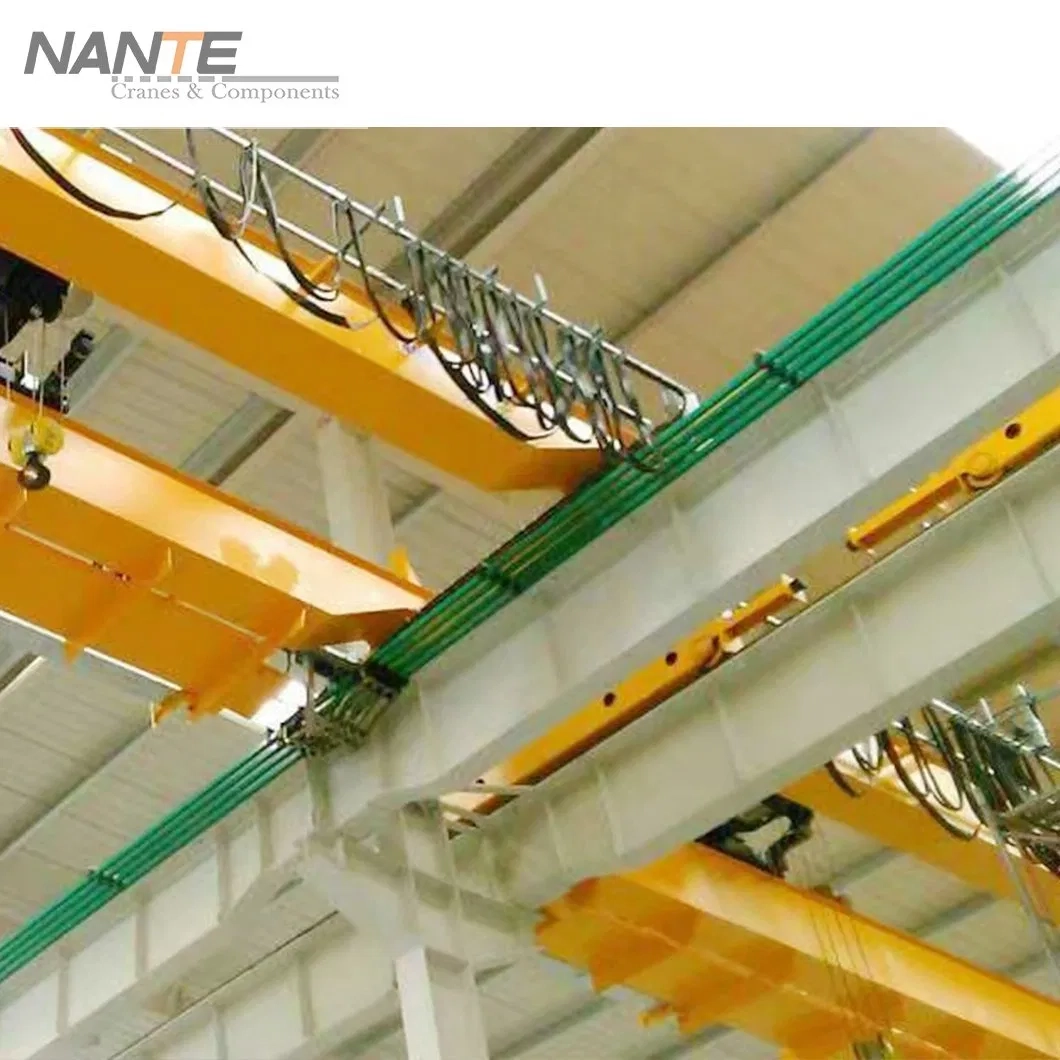
Gantry Cranes and Overhead Systems
Gantry and overhead cranes in warehouses, steel mills, and factories gain from unipole during long bridge travel. It keeps power stable in industrial halls.
Port Equipment and Container Handling Cranes
Rail-mounted gantry (RMG) and rubber-tired gantry (RTG) cranes rely on unipole for long outdoor rail travel. Copper models manage semi-gantry and port conditions well.
Heavy-Duty Industrial and Specialized Cranes
Steel mills, mining, shipbuilding, and construction depend on unipole for high-load, long-run tasks. It fits specialized heavy-duty cranes properly.
Essential Technical Parameters for Selecting Unipole Conductor Rails
Matching parameters to crane needs ensures top performance. Pay attention to capacity, spacing, and compatibility.
Current Capacity and Load Matching
Ratings range from 250A (NSP H24 aluminum) to 1600A (NSP HT32 copper). Choose based on motor/hoist power and duty cycle.
High models handle intensive work without overheating.
Optimal Installation Spacing and Support
Hanger spacing of 2-2.5m keeps stability. Adjust for vibration or thermal expansion with joints.
Proper support stops sagging over long distances.
Collector Shoe Design and System Compatibility
Copper-graphite brushes cut wear while keeping conductivity. Pressing force and alignment fit travel speeds.
Systems connect smoothly with crane travel mechanisms.
Voltage Drop Considerations and Calculation Basics for Long-Travel Setups
Voltage drop matters a lot in long-travel setups. Target <5% drop (ideally 2-3%) to keep motor efficiency.
Factors cover conductor resistance, current load, distance, temperature, and duty cycle. Larger cross-sections or copper conductors lower drop.
Basic three-phase formula: VD = √3 × I × L × R / 1000 (VD in volts, I in amps, L in meters, R in Ω/km).
Use manufacturer tools or check standards for accurate estimates. Multiple feeds or thicker rails help control high drop. (Suggested image: Voltage drop graph or calculation example for long crane runway.)
Installation Best Practices for Long-Travel Crane Efficiency
Align rails carefully along the runway centerline. Place feed points in central or smart spots for even distribution.
Add expansion joints for temperature changes. Follow rules for hangers, joints, and collector alignment. (Suggested image: Schematic of unipole installation along a crane runway with feed points and supports.)
Comparison: Unipole vs. Other Crane Power Supply Options
Unipole beats festoon cables (which tangle easily) and cable reels (limited by length) on long distances. It gives higher capacity and easier setup than enclosed rails in normal conditions.
Rail systems bring high efficiency, low energy use, and fit for hundreds of meters.
Ready to Optimize Your Long-Travel Crane Power Supply?
Nante Crane is a leading manufacturer of cranes and crane components with more than 30 years of experience, specializing in reliable solutions like unipole conductor rails for demanding applications. Our products emphasize safety, efficiency, and customization for global industries including ports, gantry, and heavy-duty cranes. Contact us today for expert guidance on selecting the ideal unipole conductor rail system for your project.
FAQ
What is the main advantage of unipole conductor rail for long-travel cranes?
It minimizes voltage drop and delivers stable high-current power over extended distances with straightforward installation.
How does unipole differ from enclosed conductor rail in crane applications?
Unipole supports higher currents (up to 1600A) and simpler setups for long spans, while enclosed offers better protection in harsh environments.
What current capacities are typical for unipole systems?
From 250A to 1600A, varying by model (aluminum or copper) and configuration.
Is unipole suitable for outdoor port cranes?
Yes, especially copper versions for semi-gantry and outdoor port applications.
How to calculate voltage drop in long-travel setups?
Apply the three-phase formula VD = √3 × I × L × R / 1000; factor in resistance, load, distance, and temperature—consult manufacturer data for accuracy.