English



Overhead Crane Seismic Design: Runway Loads, Wheel Uplift, Restraints, and Controls
Overhead Crane Seismic Design: Runway Loads, Wheel Uplift, Restraints, and Controls
Date: 2026-08-06 Share:
Overhead crane seismic design requires a coordinated review of the crane, runway, building structure, anchorage, and electrical controls. A reliable specification must define crane runway seismic loads and evaluate overhead crane wheel uplift and anti-derailment restraints before fabrication begins. The project team must also confirm how the crane will stop, hold a suspended load, and prevent automatic restart when earthquake shaking interrupts power.

Why Overhead Crane Seismic Design Requires a System Approach
An overhead crane does not resist earthquake forces as an isolated machine. The crane mass transfers inertia through the bridge, wheels or restraints, rails, runway girders, bracing, and foundations. A weak interface can interrupt this load path even when the main crane girders remain within their strength limits.
The project design basis must define whether the required performance includes collapse prevention, derailment prevention, secure load holding, or controlled shutdown. International crane design principles support agreement between purchasers and manufacturers on loads, load combinations, and calculation methods, but each project specification must identify its actual seismic inputs and acceptance criteria.
Define the Seismic Design Basis
The purchaser should provide the governing code, site coordinates, site classification, design spectral parameters, vertical seismic requirement, facility importance, and required performance level.
The structural engineer should also provide the expected motion at runway elevation. The supporting building can amplify or modify earthquake motion, so a generic ground acceleration from another project cannot provide a reliable design basis.
Calculate Crane Runway Seismic Loads in Both Directions
Crane runway seismic loads act in the longitudinal, transverse, and sometimes vertical directions. The analysis must evaluate positive and negative loading because earthquake forces can reverse direction.
Transverse and Longitudinal Seismic Actions
Transverse action acts across the runway and can load wheel flanges, guide rollers, anti-derailment restraints, rails, clips, runway-girder top flanges, and building bracing.
The lateral force can also create runway-girder torsion because the force acts near rail level rather than through the girder’s shear center.
Longitudinal action acts along the runway. The force can pass through wheel-rail friction, travel drives, brakes, end stops, parking restraints, or dedicated anchors.
The designer should not replace the seismic force with a normal bridge braking force. The two forces represent different loading events and may follow different paths into the supporting structure.
Crane Mass and Critical Positions
The seismic mass should include the bridge, end trucks, trolley, hoisting machinery, controls, platforms, and significant fixed components. The purchaser must also state whether a suspended load participates in the seismic condition.
The analysis should compare critical trolley and bridge positions. A loaded condition may govern maximum wheel compression, while an unloaded or eccentric trolley condition may govern wheel uplift.
Evaluate Overhead Crane Wheel Uplift and Anti-Derailment Restraints
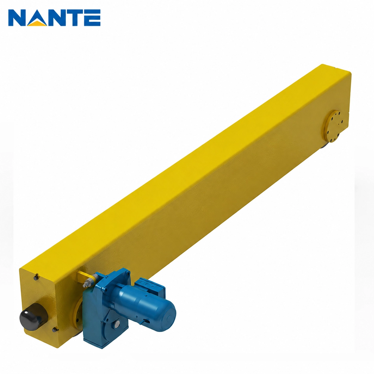
Overhead crane wheel uplift and anti-derailment restraints require separate functional checks. Vertical acceleration, transverse overturning effects, trolley eccentricity, bridge torsion, and unequal support movement can reduce one or more wheel reactions to zero.
Research into rail-mounted crane behavior shows that uplift and derailment can occur before the primary crane structure reaches a major structural damage state. The wheel-rail interface can therefore govern the seismic response even when the bridge frame retains substantial strength.
Distinguish Each Restraint Function
An anti-uplift device limits upward movement of a wheel or end truck. An anti-derailment device limits transverse movement away from the runway.
A guide roller controls lateral position before major separation occurs. A capture device provides secondary retention after normal wheel-rail contact is lost.
The designer must verify the restraint bracket, bolts, welds, supporting plates, and connected runway structure. The complete assembly must resist load reversal and combined uplift, transverse, and longitudinal forces.
Control Restraint Clearance
The restraint needs enough clearance to avoid interference during normal crane travel. The clearance calculation should include:
- The rail installation tolerance must be included.
- The wheel and flange tolerances must be included.
- The bridge skew allowance must be included.
- The runway deflection must be included.
- The temperature movement must be included.
- The predicted building displacement must be included.
Excessive clearance can allow greater relative movement before engagement and can increase impact force. The calculation report should state the selected gap, engagement direction, stiffness assumption, and design reaction.
Coordinate Rails, Runway Girders, and the Building
The crane supplier and building structural engineer must exchange both forces and movements.
The crane supplier should provide wheel reactions, uplift forces, restraint reactions, end-stop forces, and force application points. The building engineer should provide support stiffness, runway displacement, rail-gauge change, and a complete load path to the foundations.
Verify Rails, Clips, and Anchorage
Rail clips and their bolts must resist the calculated transverse demand while remaining compatible with the specified longitudinal rail movement.
Runway-girder checks should cover flange bending, torsion, lateral stability, diaphragms, and bracing connections. The building design must carry every horizontal reaction from the rail level to the foundations.
Anchor bolts and embedded plates must be checked for tension, shear, interaction, plate bending, concrete failure modes, and load reversal. A strong anchor cannot compensate for a weak bracket, weld, runway flange, column connection, or foundation.
Address Differential Structural Movement
The two runway lines can move by different amounts during an earthquake. Adjacent bays and separate building sections can also respond differently.
The project team should define the allowable rail-gauge variation, relative support displacement, runway elevation difference, and travel restrictions near structural separation joints.
Specify Power-Loss Braking and Control Requirements
The control specification must define the safe state for the hoist, trolley, and bridge.
A holding brake prevents motion when power is off. Applicable U.S. workplace requirements state that each independent hoisting unit must have a self-setting holding brake and that the hoist holding brake must apply automatically when power is removed.
The control logic should also prevent automatic restart after power restoration. The crane should require an intentional reset or valid operating command before any motion resumes.
Define the Seismic Stop Sequence
The control narrative should identify:
- The system must identify the seismic trigger source.
- The system must define the bridge and trolley response.
- The system must define the hoist and brake response.
- The system must define the main contactor state.
- The system must provide a visible fault indication.
- The system must require an intentional reset.
The specification should distinguish a seismic stop from normal stopping, emergency stopping, and an uncontrolled loss of incoming power.
The control panels, internal components, power supply, and moving cables should also have defined seismic supports and movement capacity.
Apply Project-Specific Inputs in High-Seismic Markets
Projects on the U.S. West Coast should use adopted codes and location-specific design ground motions. Official U.S. design tools provide risk-targeted ground-motion values for current structural design procedures.
Projects in Japan should use location-specific hazard and site-amplification data. Japan’s official seismic information system provides probabilistic hazard maps, hazard curves, scenario data, site-amplification factors, and subsurface information.
Projects in Chile should use the applicable code and current national hazard information. Chile’s national seismological authority released updated probabilistic seismic hazard maps in July 2026, including an interactive platform for location-specific information.
Projects in Turkey should use official coordinate-based hazard data and applicable building earthquake requirements. Turkey’s current hazard map uses peak ground acceleration values instead of the former broad earthquake-zone classification.
Middle Eastern projects must identify the exact country, city, approval authority, site class, adopted code, and owner requirements. A supplier should not transfer a seismic coefficient from one national jurisdiction to another.
Include Confirmed Seismic Data in the RFQ
A complete RFQ should provide enough confirmed information for suppliers to prepare technically comparable proposals.
- The RFQ must identify the project location, code edition, site class, spectral parameters, vertical component, importance classification, and performance objective.
- The RFQ must identify the crane capacity, span, runway length, lifting height, duty classification, trolley arrangement, and crane mass limit.
- The RFQ must define the suspended-load assumption, hook height, trolley position, bridge position, parking condition, and allowable wheel uplift.
- The RFQ must provide the rail section, fastening arrangement, runway geometry, bracing, support stiffness, and relative structural displacement.
- The RFQ must define power-loss braking, load holding, seismic shutdown, manual reset, restart prevention, and control-panel support.
- The RFQ must require reaction envelopes, restraint drawings, anchorage loads, interface drawings, a calculation report, and a control narrative.
FAQ
Does Every Overhead Crane Require Seismic Design?
The applicable code, site hazard, facility importance, supporting structure, and owner specification determine the requirement. The purchaser and structural engineer should confirm the design basis before requesting a quotation.
Can Wheel Flanges Prevent Seismic Derailment?
Wheel flanges can provide lateral guidance, but they may not control wheel uplift or large relative movement. The designer should evaluate the complete wheel, rail, guide, clearance, and secondary-restraint geometry.
What Seismic Reactions Should the Crane Supplier Provide?
The supplier should provide maximum and minimum wheel reactions, uplift forces, transverse reactions, longitudinal reactions, restraint forces, end-stop forces, anchorage loads, and the controlling load cases.
What Should Happen After Earthquake-Related Power Loss?
The hoist holding brake should apply, the system should prevent uncontrolled load descent, and travel motions should enter the specified safe state. Restored power should not cause automatic crane movement.
Submit Confirmed Seismic Crane Requirements
Nante Crane designs and manufactures overhead cranes, gantry cranes, hoisting equipment, travel mechanisms, mobile power-supply systems, rails, crane components, and control panels for international material-handling projects. Nante Crane offers long-travel, hoisting, and integrated control-panel configurations for different crane control scopes.
Project teams can submit the confirmed crane capacity, span, runway arrangement, seismic parameters, structural movement limits, suspended-load assumption, restraint objective, power supply, and braking logic. Contact Nante Crane to discuss your confirmed project requirements and receive a focused technical response for your crane application.